Some pointless fun with C# and the Grasshopper timer

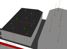
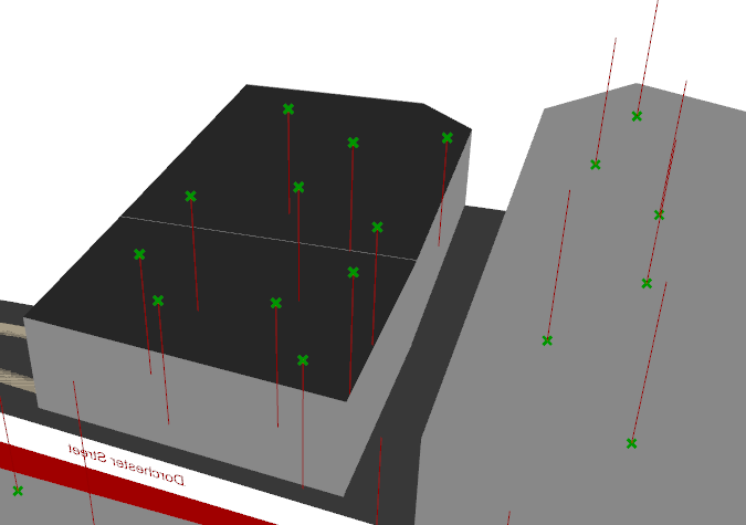
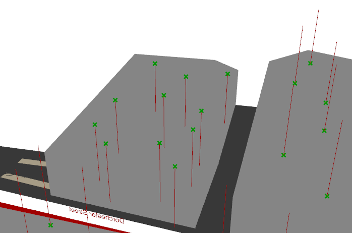
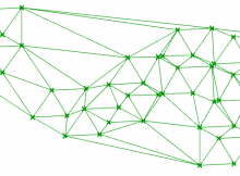
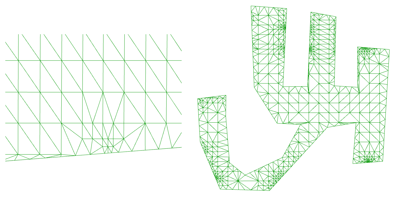
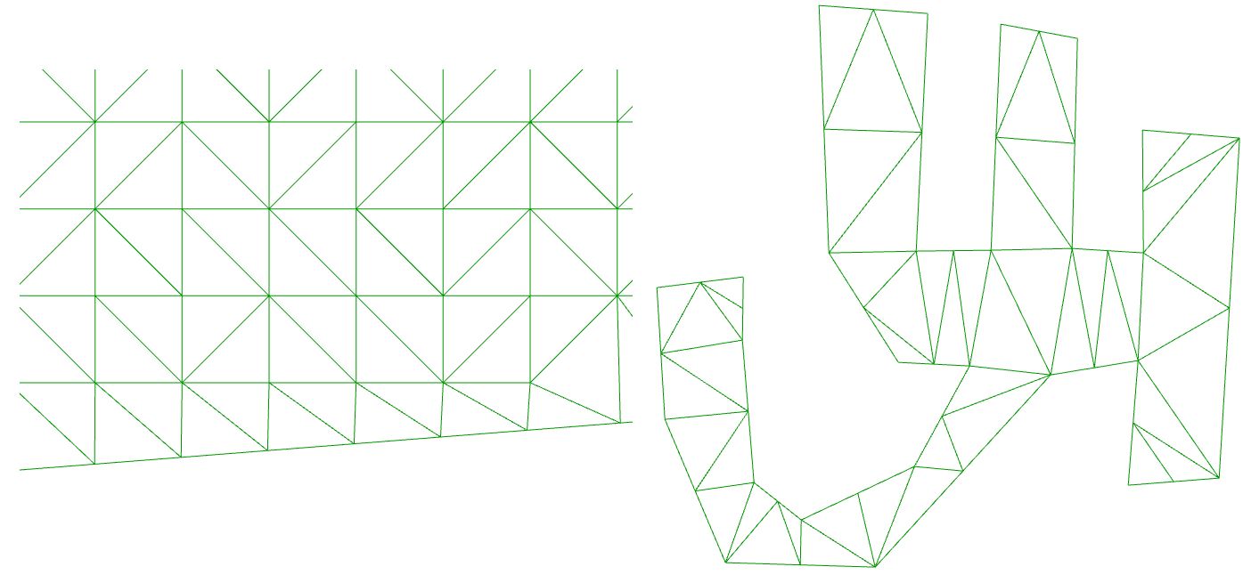
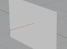
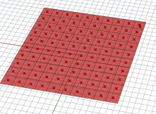
I made a thing, and it ripples!

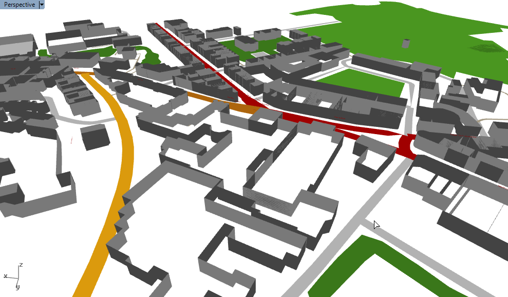
It could be sound in an auditorium. It could be waves in water. It could be energy dissipating from an earthquake’s epicentre. But that’s not the point.

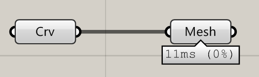
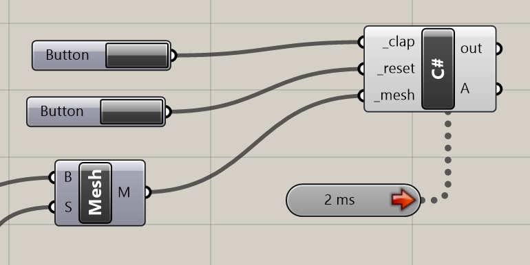
What it is is a great demonstration on what you can make with the Grasshopper timer, and bit of C#, and 15 minutes to kill.

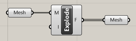
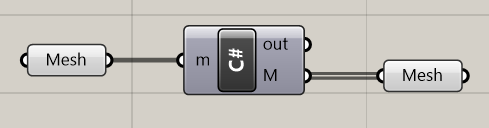
In the C# component, there are two regions you can edit: the RunScript section, and the ‘additional code’ section. Data stored in RunScript is volatile – it gets deleted every time the component is run. But data stored in the second region is preserved.

By running a timer on our component, it will be executed repeatedly. We can use this second region to hold information between these executions, allowing us to build up complex and dynamic behaviour in Grasshopper.

Grasshopper component C# timer example

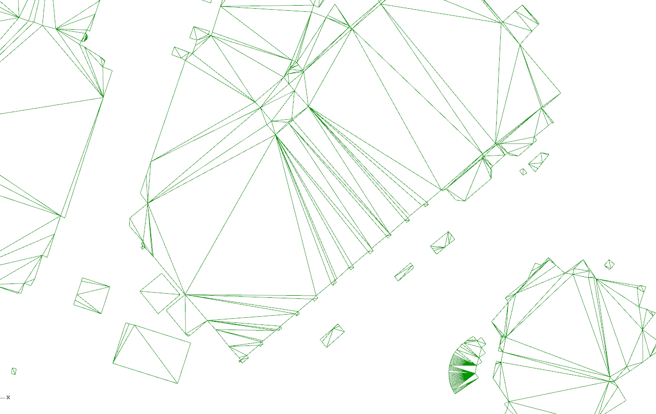
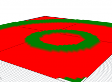
The code within the C# component handles each ‘frame’ of the animation. It maintains the current time (increasing by 1 for each cycle) and uses this time to decide what colour each part of the mesh will be.

  private void RunScript(bool _clap, bool _reset, Mesh _mesh, ref object A)
  {
    
    thetime++;

    //button actions
    if(_clap)
    {
      times.Add(thetime);
    }
    if(_reset)
    {
      times.Clear();
      thetime = 0;
      CalcDistances(_mesh, new Point3d(0, 0, 0));
    }

    //maintain list size to maintain performance
    if(times.Count > 50) times.RemoveAt(0);

    //calculate mesh colours
    _mesh.VertexColors.Clear();
    int i = 0;
    foreach(var v in _mesh.Vertices)
    {
      bool shouldbegreen = false;
      foreach(var time in times)
      {
        if(thetime == (time + (int) (distances[i])))
        {
          shouldbegreen = true;
        }
      }
      if(shouldbegreen)
      {
        _mesh.VertexColors.Add(Color.Green);
        _mesh.Vertices.SetVertex(i, _mesh.Vertices[i].X, _mesh.Vertices[i].Y, 1);
      }
      else
      {
        _mesh.VertexColors.Add(Color.Red);
        _mesh.Vertices.SetVertex(i, _mesh.Vertices[i].X, _mesh.Vertices[i].Y, 0);
      }
      i++;
    }

    //output
    A = _mesh;
  }

  // <Custom additional code> 

  int thetime = 0;
  List<int> times = new List<int>();
  List<double> distances = new List<double>();
  
  //preprocessed here to speed up calculation
  public void CalcDistances(Mesh msh, Point3d pt)
  {
    distances.Clear();
    foreach (var v in msh.Vertices)
    {
      distances.Add(pt.DistanceTo(v));
    }
  }

Triangulate a quad mesh in C#

How to take a mesh of quad faces and return a mesh with triangle faces.

The principle of the algorithm is to look at each quad and split them into two triangles. It chooses the split by the shortest diagonal across the quad.

The code is written in C# for Rhino/Grasshopper, using the Rhino mesh structure. However, it can be easily adapted to any mesh application.

  public Mesh Triangulate(Mesh x)
  {
    int facecount = x.Faces.Count;
    for (int i = 0; i < facecount; i++)
    {
      var mf = x.Faces[i];
      if(mf.IsQuad)
      {
        double dist1 = x.Vertices[mf.A].DistanceTo(x.Vertices[mf.C]);
        double dist2 = x.Vertices[mf.B].DistanceTo(x.Vertices[mf.D]);
        if (dist1 > dist2)
        {
          x.Faces.AddFace(mf.A, mf.B, mf.D);
          x.Faces.AddFace(mf.B, mf.C, mf.D);
        }
        else
        {
          x.Faces.AddFace(mf.A, mf.B, mf.C);
          x.Faces.AddFace(mf.A, mf.C, mf.D);
        }
      }
    }

    var newfaces = new List<MeshFace>();
    foreach (var mf in x.Faces)
    {
      if(mf.IsTriangle) newfaces.Add(mf);
    }

    x.Faces.Clear();
    x.Faces.AddFaces(newfaces);
    return x;
  }

Before and after:

triangulate mesh

Orient a Grasshopper mesh so that its normals face upwards

How to read the normal of a mesh in Grasshopper in C#, and flip the mesh if the normals are facing the wrong way.

Creating city buildings in Rhino

I recently revisited the task of generating cities in Rhino using Elk. One of the problems with this original solution was that I had no fast way of generating the roofs of the buildings. The most obvious solution to generate the building roofs was to use the ‘patch’ function of Rhino using the building outline as input. But surfaces are data- and processor-heavy, and files at the city scale would crash the computer. So I left the roofs out…

Rendering Park Street in Bristol in Grasshopper and Rhino using the Elk plugin and OpenStreetMap data.

Meshes are much lighter data structures than surfaces, and should be used where possible where performance is an issue. In this post, meshes were created by casting curves to meshes.

Mesh orientation

This works well, but the output meshes do have rendering issues. All mesh faces have a direction (a front and a back) and Rhino renders the mesh differently depending on what side it thinks it’s looking at. It is apparently quite random whether the above meshing trick generates a mesh which faces upwards or downwards.

Grasshopper mesh vector orientation problem on buildings

Flip backwards meshes

The solution is to ‘flip’ the offending meshes so that all meshes are facing the same way. The challenge lies in detecting the meshes which are facing the wrong way, and then to find a way to flip these meshes. The tidiest way is to do this with a C# component.

  private void RunScript(object x, object y, ref object A)
  {

    Mesh mesh = (Mesh) x;
    for(int i = 0; i < mesh.Faces.Count; i++)
    {
      var normal = mesh.Normals[0];
      if(normal.Z < 0)
      {
        mesh.Flip(true, true, true);
      }
    }

    A = mesh;

  }

The result is that the roofs now are all the same colour. The red lines, representing the normals of the mesh faces, are all now facing the same direction.

Grasshopper vectors on mesh direction problem

Convert a Brep to a Mesh in Rhino/Grasshopper C#

How to convert a Rhino Brep to a Rhino Mesh using RhinoCommon. This method is suitable for use in Grasshopper development and the Grasshopper C# component.

Create meshes from Brep

The code below produces a list of customised meshes based upon an input Brep and some mesh settings. The examples are written as static extension classes for compiled components (so you can access it directly as a Brep method), though can be easily adapted for the C# component too.

        public static List<Mesh> BrepToMeshes(this Brep brep, double maxEdge)
        {
            Mesh[] mesh;
            MeshingParameters mp = new MeshingParameters();
            mp.MaximumEdgeLength = maxEdge;
            mesh = Mesh.CreateFromBrep(brep, mp);
            return mesh.ToList<Mesh>();
        }

This method essentially replicates the Grasshopper components below:

Grasshopper component mesh to Brep

The MeshingParameters class replicates the ‘Mesh Settings’ component. You can assign settings to your mesh by creating an instance of MeshingParameters and accessing its properties, much as I have done with MaximumEdgeLength.

Joining the meshes

The output is a list of meshes. If you want to truly replicate the Mesh Brep component, you will also need to join all meshes in the list into a single mesh. This can be done with the Append method:

        public static Mesh JoinMeshes(this List<Mesh> meshes)
        {
            var rtnmesh = new Mesh();
            foreach (Mesh mesh in meshes)
            {
                rtnmesh.Append(mesh);
            }
            return rtnmesh;
        }

And for completeness, you can call the methods in a single line:

        public static Mesh BrepToMesh(this Brep brep, double maxEdge)
        {
            return JoinMeshes(BrepToMeshes(brep, maxEdge));
        }

Create 2D Delaunay triangulation mesh with C# in Grasshopper

How to perform a Delaunay triangulation on a list of points mapped in 2D, using the C# component in Grasshopper.

Delaunay triangulation is a highly efficient algorithm which creates a triangulated mesh from a collection of points. This page shows how to create a 2D mesh from a collection of points on the XY plane.

Input

A list of Point3d. These points should already be mapped onto a 2D plane – ideally onto the XY plane.

Points Grasshopper for Delaunay triangulation

If your points aren’t mapped onto a 2D plane, you’ll need to do this in advance. The reason for this is that the Delaunay triangulation algorithm below uses the Node2 type – essentially like a point, but only with X and Y coordinates – since this algorithm produces a 2D mesh.

Output

A regular, Grasshopper-friendly mesh.

Delaunay mesh in Grasshopper with C#

Steps

  1. Convert Point3d into Node2
  2. Add Node2 to Node2List (that’s a list of Node2s, not “node-to-list”!)
  3. Calculate connectivity of mesh faces
  4. Construct and return mesh

C# code

The code below uses Grasshopper.dll to perform the Delaunay triangulation.

    //input
    List<Point3d> pts;

    //convert point3d to node2
    //grasshopper requres that nodes are saved within a Node2List for Delaunay
    var nodes = new Grasshopper.Kernel.Geometry.Node2List();
    for (int i = 0; i < pts.Count; i++)
    {
      //notice how we only read in the X and Y coordinates
      //  this is why points should be mapped onto the XY plane
      nodes.Append(new Grasshopper.Kernel.Geometry.Node2(pts[i].X, pts[i].Y));
    }

    //solve Delaunay
    var delMesh = new Mesh();
    var faces = new List<Grasshopper.Kernel.Geometry.Delaunay.Face>();
    
    faces = Grasshopper.Kernel.Geometry.Delaunay.Solver.Solve_Faces(nodes, 1);
    
    //output
    delMesh = Grasshopper.Kernel.Geometry.Delaunay.Solver.Solve_Mesh(nodes, 1, ref faces);

What next?

Delaunay meshes are pretty amazing. They are quick to generate, quick to analyse and quick to render. They generate sensible triangulation and require no more information than the input points. Unless you absolutely must have smooth surfaces and edges, don’t use a surface, use a mesh.

This video uses Delaunay triangulation to power the graph in the bottom left. The graph was easily coloured by associating each node in the mesh with a value.

These posts will help you get started in making the most of your mesh:

References

FastMesh v2: The stupidly easy way of creating efficient meshes from polylines

In a recent post, I found that converting polylines to meshes in Grasshopper can be problematic. Using a patch to create a mesh from a curve is slow, and directly converting from a curve to a mesh resulted in an inefficent mesh with too many faces.

curve-to-mesh

Mesh in Grasshopper

It seemed that in Grasshopper, there was no easy way to create efficient meshes from closed polylines, so I set about creating my own component. It produced meshes like this:

A simple mesh in Rhino, created in Grasshopper

But in cases with more complicated geometry, it didn’t always work – in the details, it would sometimes miss out triangles, or the mesh edge didn’t quite line up with the original boundary.

Revisiting the problem today, my colleague David Greenwood pointed me towards a method he’d found within the Rhino API – and we can access it in both the C# component and through visual studio. This method produces a mesh from a closed polyline – but amazingly, it returns the kind of efficient mesh we were wanting all along. And as a bonus, it’s really fast too!

The command you need is very simple:

A = Rhino.Geometry.Mesh.CreateFromClosedPolyline(pline);

We tried this method to create the roof tops of a whole city centre, with over 11000 building outlines as polylines. This is the result:

manchester-roof-mesh

Click the image above for full size.

Zooming in on an image, we can see that, bearing in mind that mesh faces like to be in triangles, the meshes seem to be roughly as efficient as we could imagine:

manchester-roof-mesh-close

And how long did these 11000 meshes take to generate? About half a second!

mesh-from-curve-timer

And if, instead of using the C# component, we write the code into a compiled component, such as when we create components with Visual Studio, the time is less than 300ms.

And if that is still too slow, we could also parallelise it, potentially bringing that time under 100ms.

So much for ripping out my hair trying to write my own algorithm or dig around for one elsewhere – I needn’t have bothered because it’s already implemented in Rhino!

How to explode a mesh in Grasshopper

Exploding a mesh is a key skill in handling meshes. Knowing the different ways is a good way of demonstrating you understand how to manipulate meshes. You might need to redefine some faces in your mesh, or you might want to colour a mesh face-by-face.

What does it mean to explode a mesh? It essentially means taking each face of the mesh, and making it a separate mesh in its own right. So a single mesh with 100 faces will become 100 meshes with one face.

There are broadly three ways of exploding a mesh, depending on what you want to do, your ability level, and the wider task you are trying to achieve. Let’s say we want to explode the mesh below.

Rhino mesh grid

Starting with the easiest…

Method 1: Use MeshEdit

Use the Explode component in the MeshEdit collection of components:

Grasshopper explode mesh with MeshEdit component

Notice how we feed a single mesh into the left, and a list comes out the other end.

This method is dependent upon MeshEdit being installed on the computer that the Grasshopper file is being used on. In cases where you can’t rely on this, for example in team working or when sharing files with clients, you might want to try…

Method 2: Use native Grasshopper components

Use this slightly clunkier method which grafts mesh data to create multiple meshes. The two components are ‘Construct Mesh’ and ‘Deconstruct Mesh’. Take care of the grafts and flattens. You could always turn these into a cluster for tidiness.

Explode Grasshopper mesh with native Grasshopper components

Method 3: Use C#

If you are writing C# and want to merge the mesh explode into a script for efficiency, or you just want to show off your Grasshopper Geek credentials, you can use the following method:

  List<Mesh> Explode(Mesh m)
  {
    var rtnlist = new List<Mesh>();

    for (int f = 0; f < m.Faces.Count; f++)
    {
      var newmesh = new Mesh();
      newmesh.Vertices.Add(m.Vertices[m.Faces[f].A]);
      newmesh.Vertices.Add(m.Vertices[m.Faces[f].B]);
      newmesh.Vertices.Add(m.Vertices[m.Faces[f].C]);
      if(m.Faces[f].IsQuad) newmesh.Vertices.Add(m.Vertices[m.Faces[f].D]);

      if(m.Faces[f].IsTriangle) newmesh.Faces.AddFace(0, 1, 2);
      if(m.Faces[f].IsQuad) newmesh.Faces.AddFace(0, 1, 2, 3);

      rtnlist.Add(newmesh);
    }

    return rtnlist;
  }


…which you can easily call with:

    M = Explode(m);


This gives a nice, tidy component:

Explode mesh in Grasshopper C# component

Learning to manipulate meshes in C# is a great skill to have, and I recommend you get into it. Recently, I have used C# to turn curves into data-light meshes, and to turn curves into roads suitable for mapping.

Whichever method you’ve chosen, if you bake the result, you should end up with something like this:

Exploded Rhino grid mesh

Mesh line intersections in Grasshopper in C#

Many intersection checks are possible in C# in Grasshopper, although finding them isn’t entirely intuitive.

One task I wanted to do today was to see if a ray of light between one point and another was being blocked by a mesh. This requires a mesh-line intersection check – to check if the ray of light was being blocked by the mesh.

How to calculate an intersection

You can find a lot of intersection methods for different kinds of geometry under Rhino.Geometry.Intersection. The mesh line intersection is a good choice as it is one of the faster intersection checks – especially compared to anything involving surfaces.

To do the intersection check, we need our mesh and our ray. The ray can be a bit challenging to set up – it’s a common mistake to forget to realise that your line start and end points might be touching the mesh, which would lead to positive intersection results. This is why I’ve redefined my line to run from 0.001 to 0.999.

        //collision test
        var ln = new Line(e[em], centre); //ray
        var startpt = new Point3d(ln.PointAt(0.001)); //modify ray so start/end don't intersect
        var endpt = new Point3d(ln.PointAt(0.999));
        ln.From = startpt;
        ln.To = endpt;
        Int32[] intersections; //where intersection locations are held
        Rhino.Geometry.Intersect.Intersection.MeshLine(r, ln, out intersections);

        //calculate emission contribution and add to that receiver
        if(intersections == null)
        {
          //if no intersections, we can assume ray is unimpeded and do our calcs
          double contribution = Math.Cos(alpha) / (dist * dist);
          rtnvals[f] += Math.Max(contribution, 0);
        }

Area of a mesh face in C# in Grasshopper

Another quick script for handing meshes – this time to find the area of a mesh face.

This script is in C# and can be easily used with the C# component in Grasshopper. Copy the script into the ‘custom additional code’ section. It is written as a method, so you can easily call it. In the ‘RunScript’ section, call the method with something like:

double area = Area(3, myMesh)

This will return the area of the third face in the mesh called myMesh.

The method itself to calculate the area of a mesh face is below. Of course, you can use this method in any C# application, not just Grasshopper – you’ll just need to modify the code to fit whatever data structure your mesh uses.

  double Area(int meshfaceindex, Mesh m)
  {
    //get points into a nice, concise format
    Point3d[] pts = new Point3d[4];
    pts[0] = m.Vertices[m.Faces[meshfaceindex].A];
    pts[1] = m.Vertices[m.Faces[meshfaceindex].B];
    pts[2] = m.Vertices[m.Faces[meshfaceindex].C];
    if(m.Faces[meshfaceindex].IsQuad) pts[3] = m.Vertices[m.Faces[meshfaceindex].D];

    //calculate areas of triangles
    double a = pts[0].DistanceTo(pts[1]);
    double b = pts[1].DistanceTo(pts[2]);
    double c = pts[2].DistanceTo(pts[0]);
    double p = 0.5 * (a + b + c);
    double area1 = Math.Sqrt(p * (p - a) * (p - b) * (p - c));

    //if quad, calc area of second triangle
    double area2 = 0;
    if(m.Faces[meshfaceindex].IsQuad)
    {
      a = pts[0].DistanceTo(pts[2]);
      b = pts[2].DistanceTo(pts[3]);
      c = pts[3].DistanceTo(pts[0]);
      p = 0.5 * (a + b + c);
      area2 = Math.Sqrt(p * (p - a) * (p - b) * (p - c));
    }

    return area1 + area2;
  }

This script is based upon Heron’s Formula, which calculates the area of a triangle based upon knowing its three lengths. The script also calculates the area for quads. It does this by dividing the quad into two triangles.

mesh-area

C# code for getting the centrepoint of a mesh face in Grasshopper

A method I quickly wrote to get the centrepoint of a mesh face using the C# component in Grasshopper. More information about the mesh data structure used to generate this code is in this post.

The method essentially calculates the ‘average’ location of each of the 3 or 4 nodes on the mesh. (Formally, this is a simplification of the first moment of area.)

  Point3d CentrePoint(int meshfaceindex, Mesh m)
  {
    var temppt = new Point3d(0, 0, 0);

    temppt.X += m.Vertices[m.Faces[meshfaceindex].A].X;
    temppt.Y += m.Vertices[m.Faces[meshfaceindex].A].Y;
    temppt.Z += m.Vertices[m.Faces[meshfaceindex].A].Z;

    temppt.X += m.Vertices[m.Faces[meshfaceindex].B].X;
    temppt.Y += m.Vertices[m.Faces[meshfaceindex].B].Y;
    temppt.Z += m.Vertices[m.Faces[meshfaceindex].B].Z;

    temppt.X += m.Vertices[m.Faces[meshfaceindex].C].X;
    temppt.Y += m.Vertices[m.Faces[meshfaceindex].C].Y;
    temppt.Z += m.Vertices[m.Faces[meshfaceindex].C].Z;

    if(m.Faces[meshfaceindex].IsQuad)
    {
      temppt.X += m.Vertices[m.Faces[meshfaceindex].D].X;
      temppt.Y += m.Vertices[m.Faces[meshfaceindex].D].Y;
      temppt.Z += m.Vertices[m.Faces[meshfaceindex].D].Z;

      temppt.X /= 4;
      temppt.Y /= 4;
      temppt.Z /= 4;
    }
    else
    {
      temppt.X /= 3;
      temppt.Y /= 3;
      temppt.Z /= 3;
    }

    return temppt;
  }

It’s sloppy to have the code so repetitive, but the .A and the .X notation don’t make for good code efficiency. It’s sometimes possible to use temppt[d] where d = 0, 1 or 2 for X, Y and Z correspondingly (which would allow the use of a ‘for’ loop), but the mesh Vertices property returns Point3f instead of Point3d, which doesn’t allow this.