How to colour a mesh using the C# component in Grasshopper

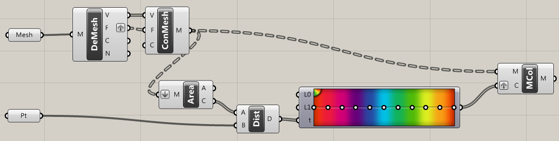
In this post, we saw how you can apply colours to a mesh using Grasshopper components.

Sometimes we would rather use C# code – in certain cases it can be a lot faster than clicking around the Grasshopper canvas, and it can give us a lot more control. How can we apply colour to a mesh using C#?

How coloured meshes work in Grasshopper

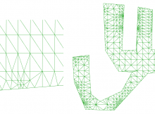
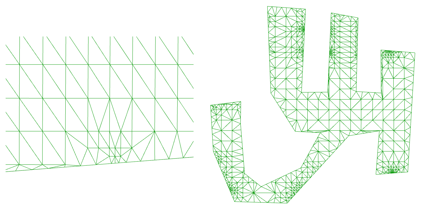
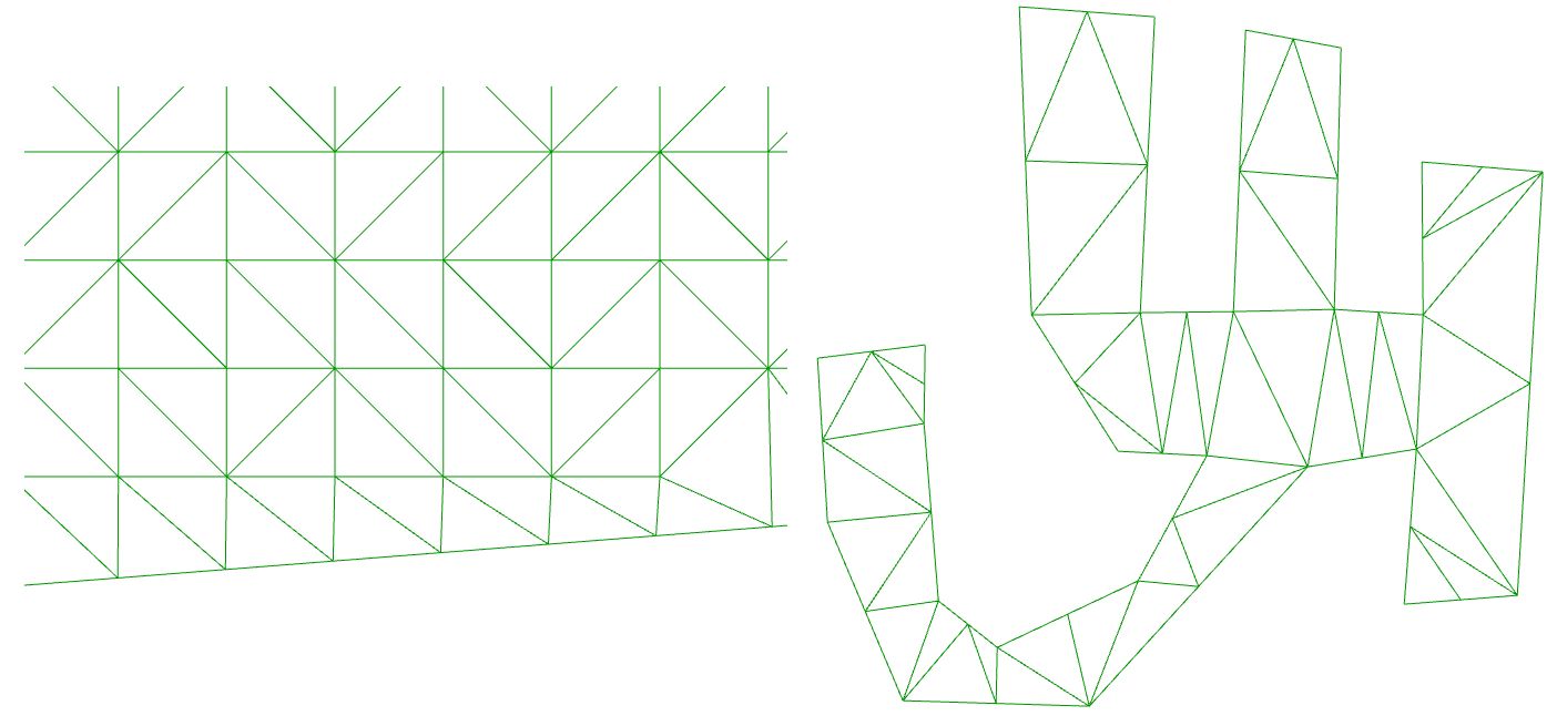
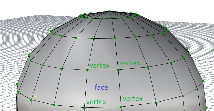
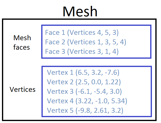
If we understand the mesh structure in Grasshopper, we know that meshes are defined by nodes and faces. We create a list of nodes, and then ‘join them up’ into faces of 3 or 4 nodes.

When we colour a mesh in Grasshopper, we do not colour the faces themselves. Instead, we set each node to a colour. So, if we have a simple mesh of one face and four nodes, we must define four colours, one for each node.

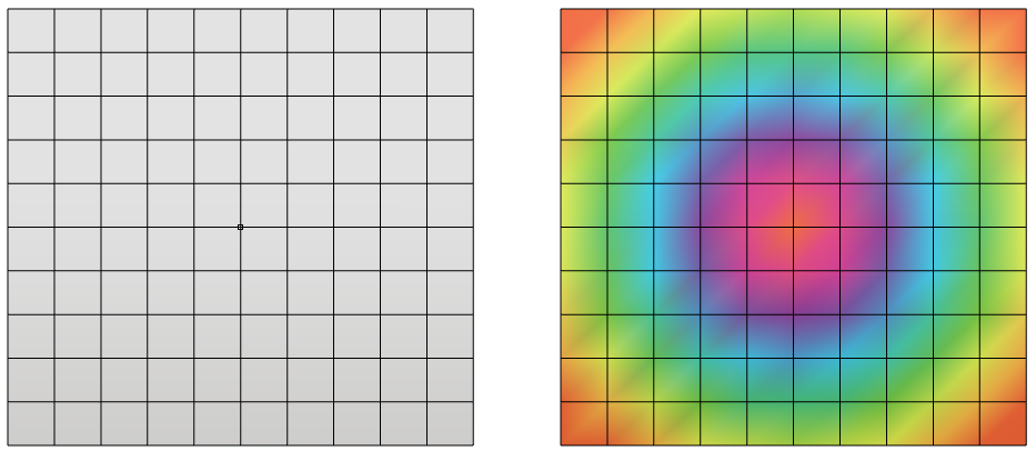
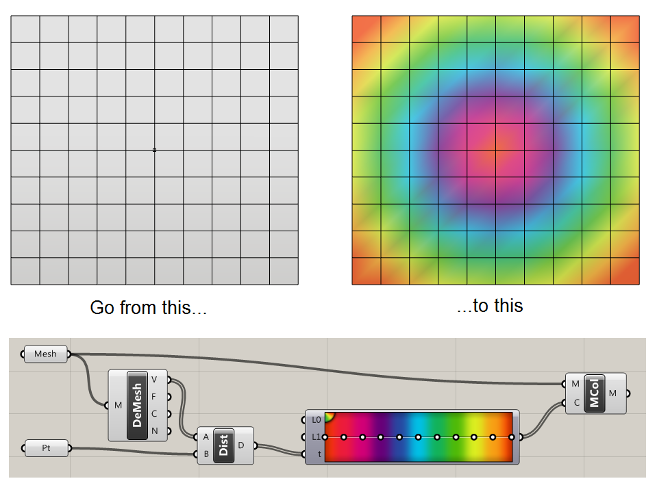
We can set the same colour to every node to get a uniform colour. But a nice thing that we can do is set different colours to each node. Rhino will automatically render the mesh with smooth colour gradients – nice!

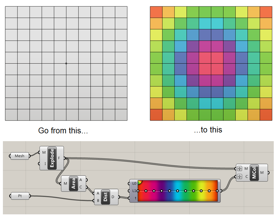
As an aside, if you want one uniform colour per face, as in the second example here, we must again explode the mesh into multiple meshes, one per face. Alternatively, instead of exploding, you could duplicate the nodes at points where faces of different colours meet.

An example

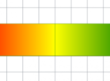
Let’s say you want to create a mesh with a 3-colour gradient of red, yellow and green, as below:

Grasshopper mesh 3 colour gradient

We can create this with a mesh of 2 faces and 6 nodes. Create a C# component within Grasshopper with default input/outputs, and copy the code below:

    //declare an empty mesh
    var mesh = new Mesh();

    //create vertices
    mesh.Vertices.Add(0, 0, 0);
    mesh.Vertices.Add(5, 0, 0);
    mesh.Vertices.Add(5, 2, 0);
    mesh.Vertices.Add(0, 2, 0);
    mesh.Vertices.Add(10, 0, 0);
    mesh.Vertices.Add(10, 2, 0);

    //create colour list. The vertex [i] is coloured by the value at VertexColors[i]
    //the VertexColors list MUST be the same length as the vertices list
    mesh.VertexColors.Add(Color.Red);
    mesh.VertexColors.Add(Color.Yellow);
    mesh.VertexColors.Add(Color.Yellow);
    mesh.VertexColors.Add(Color.Red);
    mesh.VertexColors.Add(Color.Green);
    mesh.VertexColors.Add(Color.Green);

    //create faces using vertex indices
    mesh.Faces.AddFace(0, 1, 2, 3);
    mesh.Faces.AddFace(1, 4, 5, 2);

    //return mesh
    A = mesh;

A few notes

The colours are saved as a list in VertexColors. Note that this list must either be completely empty (if you are not interested in colouring your mesh) or it should be exactly the same length as the Vertices list. Fail to do this, and your mesh will have a nasty habit of disappearing with no word of warning!

Since VertexColors is a list, once you have added colours, you can edit them in the usual way with VertexColors[i] where i is some index number. But, like a list, you cannot add a new colour using VertexColors[i] – you must use the VertexColors.Add() method.

Colours are normally defined using RGB values, for example:

Mesh.VertexColors.Add(255,0,0);

But a useful shortcut if you don’t know/can’t be bothered to look up colour codes is to use shortcuts like Color.Red instead of RGB values.

FastMesh for Grasshopper: A cluster to make fast, light meshes from curves

Creating a mesh from a curve can be challenging in Grasshopper. Most ways of doing it involve creating a surface and then meshing that surface. And once the mesh is made, it often has inconsistent face densities, with unusual points of high point density.

bad_mesh

The mathematics behind these methds are fine for the general case (any closed curve in any alignment), but in cases where we have a planar polyline (i.e. no curved segments, such as a room or building outline) and where this curve lies in the XY plane, we can use a highly optimised algorithm.

FastMesh is my attempt. Simply connect a polyline (or list of polylines) and it will mesh those curves – without the heavy operation of creating intermediary surfaces. I have attempted to ensure that points are distributed evenly in a grid-like pattern (so it is suitable for creating analysis meshes for tools like Honeybee), and you can optionally control the distance between points by inputting a distance into ‘s’. If you leave ‘s’ blank (or set it to 0) it will create a mesh with a minimum number of faces, creating extremely light meshes, for example in creating buildings with Elk.

good_mesh

The principle of my method is that it generates a collection of mesh points, and removes any mesh points that don’t lie inside the curve. It then performs a Delaunay Triangulation on remaining points. For concave shapes, triangles will be formed that fall outside the curve, which are removed.

The mesh data structure in Grasshopper

Understanding meshes in Grasshopper can be a little tricky. They have a somewhat unintuitive data structure that can make it hard to handle meshes in C# code.

You probably already know a little about meshes. They are a form of geometry that contain a collection of faces, and that each face can have no more than 4 corners. How does Grasshopper handle this?

The basics

A mesh is a collection of faces. Each face is defied by 3 or 4 vertices. A vertex is a 3D point. A single mesh can contain as many faces and vertices as you want.

A mesh sphere in Grasshopper, indicating mesh points (vertices) and mesh faces


In terms of data structures, a mesh contains 2 lists:

  • A list of faces
  • A list of vertices

Firstly, we define a list of vertices. This is a list of 3D points. For each point, we can also imagine an index. For example, the fourth point in the list has an index of 4.

Then, we define each face. For each face, we define three vertices for triangles called A, B and C, or four vertices for quads, A, B, C and D. In the face list, the vertices contain the indices for the vertices, and not the coordinates of the vertices themselves. This is important to remember!

What does this mean when Rhino reads this data and tries to display a mesh? Take the example in the image below.

A table with an example showing how mesh faces and mesh vertices are held in the mesh data structure

The mesh contains 3 faces. For the first face, we have three values and therefore three vertices, so face 1 is a triangle. What are the coordinates of these three vertices? To do this, we need to also look at the vertices list. Face 1 contains vertices 4, 5 and 3. Remember, these are the indices for our vertices. We take these three values and cross-reference them with the vertex list – reading the coordinates for vertices 3, 5 and 4.

Why is it so complicated?

The above system actually makes sense from a data efficiency point of view. Of course, in most meshes, multiple faces will share vertices. With the sphere above, each vertex is shared between 4 neighbouring faces. With the above data structure, we only need to define our mesh points once.

Furthermore, if we want to move a point on our sphere, we just have to update our vertex list. We don’t have to search for every copy of a node or worry about ‘breaking’ our mesh when we move mesh points about.

Manipulating meshes: A C# example

Create a C# component in Grasshopper. Create an input called ‘mesh’ and set its data type to Mesh.

  private void RunScript(Mesh mesh, ref object A)
  {
    //1) Let's read from an existing mesh

    //get faces from mesh
    List faces = new List();
    foreach(MeshFace face in mesh.Faces)
    {
      faces.Add(face);
    }

    //get vertices from mesh
    List vertices = new List();
    foreach(Point3d vertex in mesh.Vertices)
    {
      vertices.Add(vertex);
    }

    //2) Let's get the coordinates for a mesh face
    
    //get the indices for the 10th face
    int[] indices = new int[4];
    indices[0] = mesh.Faces[10].A;
    indices[1] = mesh.Faces[10].B;
    indices[2] = mesh.Faces[10].C;
    indices[3] = mesh.Faces[10].D;

    //We can now get the coordinates for the 10th face from these indices
    Point3d[] facepts = new Point3d[4];
    for (int i = 0; i < 4; i++)
    {
      facepts[i] = mesh.Vertices[indices[i]];
    }


    //3) Let's make a new mesh from scratch
    
    Mesh rtnmesh = new Mesh();
    //for the new mesh, we first need to define the vertices
    //we can add any points we like - let's just copy over the vertices list
    rtnmesh.Vertices.AddVertices(vertices);
    //now let's make a face and add it to the (currently empty) face list
    MeshFace tempface = new MeshFace(0, 1, 12, 11);
    rtnmesh.Faces.AddFace(tempface);

  }

Download an example

The code above is available in the file below.

Download

How to colour a mesh in Grasshopper

Let’s say that you have a mesh and a point. You want to colour the mesh according to how far the different parts of the mesh are from the point.

To do this, we need to:

  1. Import the mesh and the point into Grasshopper
  2. Calculate the distance between the different points on the mesh
  3. Apply these colours to the mesh

Colour a mesh with smooth gradients

Colour a mesh in Grasshopper - smooth


Colour a mesh with one colour per face

Colour a mesh in Grasshopper - discrete

Note that here I am using the ‘Mesh Explode’ component to break a mesh into its faces, which is part of the MeshEdit plugin for Grasshopper.

I also have grafted both inputs to ‘Mesh Colour’ – don’t forget to do this! You should quickly see why if you don’t…

If you don’t want to use MeshEdit, you can recreate the behaviour using the slightly more clunky method below:

Colour a mesh with one colour per face - Grasshopper

Finally, if you are writing script, it is also possible to colour a mesh using the C# component. See this post for more information.