Generating random numbers in C# isn’t the most intuitive process. I originally learnt to code back in the day using VB, where generating a random number was as simple as calling the Rnd() function.
In C#, there is slightly more work to do. We first have to create an instance of the Random class, which is non-static. Only then can we call a function to generate a random number for us.
The example below is written for the C# component in Grasshopper, but the gist of it can be used for any C# application.
C# code
privatevoid RunScript(refobject A)
{
var rand = new Random();
var rtnlist = new List<double>();
for (int i = 0; i < 100000; i++)
{
rtnlist.Add(rand.Next(1000));
}
A = rtnlist;
}
What’s happening here?
We create an instantiation of the Random class. We call this ‘rand’. This is what contains the logic to generate our random numbers.
Since computers are inherently quite terrible at generating truly random numbers, programming languages tend to use pre-programmed lists of random numbers instead. The random class picks a place in the list to start from. Then, every time we call for a new random number, it is simply reading the next value in the list.
This is why the function to generate a new random number is called ‘Next’ – it is simply looking at the next value in its list of random numbers. The 1000 in the brackets specifies that the number returned will be scaled between 0 and 1000. (If we left the brackets blank, the random number would be between 0 and the highest possible integer.)
The script creates a list of 100000 random numbers between 0 and 1000. The output is sent to the variable ‘A’. This is a Grasshopper specific thing – if you were writing this as a method, you could change this to ‘return rtnlist’.
If you need many random numbers, you should still only create one instance of Random, and then use ‘Next()’ to build your collection of random numbers. If you don’t do this, and instead create an instance of ‘Random’ for every random number you need, the resulting numbers may not be random at all.
A very simple approach to subdividing a mesh in Grasshopper.
What it is
You have a mesh which is made of vertices and mesh faces. Let’s say some of the faces are too large, and you want to divide these large faces into lots of smaller faces.
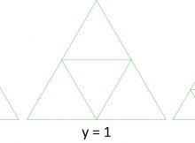
This script divides all faces into triangles. It them measures the area of each triangle. If the triangle area is above a threshold, it divides that triangle into four smaller triangles.
How to use it
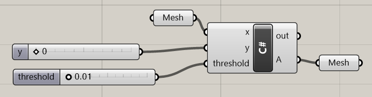
Create a C# component. Set inputs called x, y, and threshold. X is a mesh, Y is an integer, and threshold is a double.
Copy the code below into the C# component.
Feed a mesh into x. Y is the maximum number of subdivisions that will be performed on the mesh. ‘Threshold’ is the area of a ‘big’ mesh face, and the script will try to subdivide any such big faces.
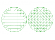
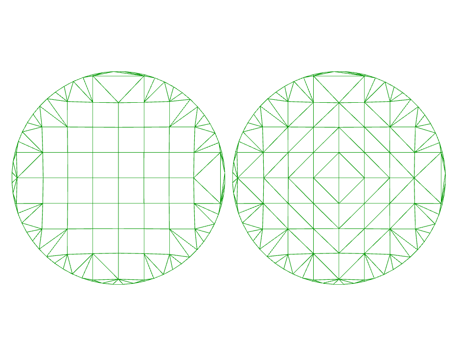
What you get
Here is a slightly more complicated example. Notice how only large faces get subdivided first.
Code
privatevoid RunScript(Mesh x, int y, double threshold, refobject A)
{
x = Triangulate(x);
for (int i = 0; i < y; i++) Subdivide(x, threshold);
A = x;
}
// <Custom additional code> public Mesh Subdivide(Mesh m, double threshold)
{
List<MeshFace> newFaces = new List<MeshFace>();
foreach (MeshFace mf in m.Faces)
{
double mfarea = AreaOfTriangle(m, mf);
if(mfarea > threshold)
{
m.Vertices.AddVertices(FaceMidPoints(m, mf));
newFaces.Add(new MeshFace(mf.A, m.Vertices.Count - 3, m.Vertices.Count - 1));
newFaces.Add(new MeshFace(m.Vertices.Count - 3, mf.B, m.Vertices.Count - 2));
newFaces.Add(new MeshFace(m.Vertices.Count - 1, m.Vertices.Count - 2, mf.C));
newFaces.Add(new MeshFace(m.Vertices.Count - 3, m.Vertices.Count - 2, m.Vertices.Count - 1));
}
else newFaces.Add(mf);
}
m.Faces.Clear();
m.Faces.AddFaces(newFaces);
newFaces.Clear();
return m;
}
public List<Point3d> FaceMidPoints(Mesh m, MeshFace mf)
{
var rtnlist = new List<Point3d>();
rtnlist.Add(MidPoint(m.Vertices[mf.A], m.Vertices[mf.B]));
rtnlist.Add(MidPoint(m.Vertices[mf.B], m.Vertices[mf.C]));
rtnlist.Add(MidPoint(m.Vertices[mf.C], m.Vertices[mf.A]));
return rtnlist;
}
public Point3d MidPoint(Point3d pt1, Point3d pt2)
{
returnnew Point3d(0.5 * (pt1.X + pt2.X), 0.5 * (pt1.Y + pt2.Y), 0.5 * (pt1.Z + pt2.Z));
}
publicstatic Mesh Triangulate(Mesh x)
{
int facecount = x.Faces.Count;
for (int i = 0; i < facecount; i++)
{
var mf = x.Faces[i];
if(mf.IsQuad)
{
double dist1 = x.Vertices[mf.A].DistanceTo(x.Vertices[mf.C]);
double dist2 = x.Vertices[mf.B].DistanceTo(x.Vertices[mf.D]);
if (dist1 > dist2)
{
x.Faces.AddFace(mf.A, mf.B, mf.D);
x.Faces.AddFace(mf.B, mf.C, mf.D);
}
else
{
x.Faces.AddFace(mf.A, mf.B, mf.C);
x.Faces.AddFace(mf.A, mf.C, mf.D);
}
}
}
var newfaces = new List<MeshFace>();
foreach (var mf in x.Faces)
{
if(mf.IsTriangle) newfaces.Add(mf);
}
x.Faces.Clear();
x.Faces.AddFaces(newfaces);
return x;
}
publicdouble AreaOfTriangle(Point3d pt1, Point3d pt2, Point3d pt3)
{
double a = pt1.DistanceTo(pt2);
double b = pt2.DistanceTo(pt3);
double c = pt3.DistanceTo(pt1);
double s = (a + b + c) / 2;
return Math.Sqrt(s * (s - a) * (s - b) * (s - c));
}
publicdouble AreaOfTriangle(Mesh m, MeshFace mf)
{
return AreaOfTriangle(m.Vertices[mf.A], m.Vertices[mf.B], m.Vertices[mf.C]);
}
Caveats
This code is WIP. It is by no means the most efficient or correct way (by a long shot!) of doing this – it merely fulfilled a task I had at the time.
It also returns what Grasshopper reckons is an ‘invalid mesh’. I suspect that this is because vertices are generated that overlap other faces without also being one of their vertices, but I’m not quite sure. Despite this warning, it does still produce a usable mesh.
Further reading
I have written about the mesh data structure here, which is probably helpful if you want to understand what’s happening in the above code.
The algorithm for calculating the area of a triangle comes from Heron’s Formula.
I have also published some C# code for triangulating a mesh here.
How to take a mesh of quad faces and return a mesh with triangle faces.
The principle of the algorithm is to look at each quad and split them into two triangles. It chooses the split by the shortest diagonal across the quad.
The code is written in C# for Rhino/Grasshopper, using the Rhino mesh structure. However, it can be easily adapted to any mesh application.
  public Mesh Triangulate(Mesh x)
  {
    int facecount = x.Faces.Count;
    for (int i = 0; i < facecount; i++)
    {
      var mf = x.Faces[i];
      if(mf.IsQuad)
      {
        double dist1 = x.Vertices[mf.A].DistanceTo(x.Vertices[mf.C]);
        double dist2 = x.Vertices[mf.B].DistanceTo(x.Vertices[mf.D]);
        if (dist1 > dist2)
        {
          x.Faces.AddFace(mf.A, mf.B, mf.D);
          x.Faces.AddFace(mf.B, mf.C, mf.D);
        }
        else
        {
          x.Faces.AddFace(mf.A, mf.B, mf.C);
          x.Faces.AddFace(mf.A, mf.C, mf.D);
        }
      }
    }

    var newfaces = new List<MeshFace>();
    foreach (var mf in x.Faces)
    {
      if(mf.IsTriangle) newfaces.Add(mf);
    }

    x.Faces.Clear();
    x.Faces.AddFaces(newfaces);
    return x;
  }
I have recently been constructing whole cities in Rhino using the Elk plugin. This parses OpenStreetMap data into Grasshopper geometry, allowing you to visualise any city or area in the world in your Rhino viewport.
One of the most interesting ways of getting your cities to look like cities is getting the buildings right. It is possible to extract building data with Elk, but this isn’t intuitive if you aren’t already familiar with OpenStreetMap data. And even if you are, the output is a collection of points, which requires further work to turn it into actual buildings.
This article will show you how I created buildings by extracting the OSM data and converting them into 3D meshes.
OpenStreetMap: Understanding the data
A crash course into OpenStreetMap data: All (well, nearly all) objects in the map are either saved as points or as lists of points. Points are useful for small objects, such as benches, letterboxes or trees. For larger objects, such as roads and buildings, collections of points are used. For roads, these points join together to form lines along the centre of the road. For buildings, these points define the line around the building’s edge. These ‘point collections’ are essentially polylines.
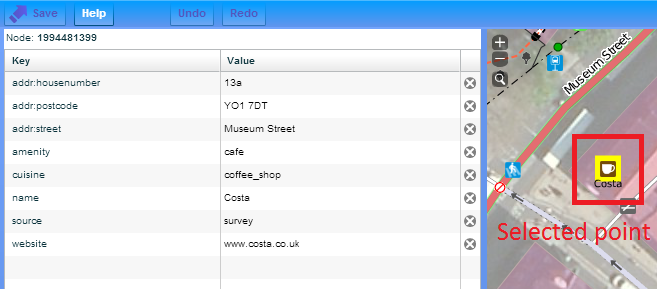
Every object, whether a point or a polyline, has a list of data associated with it. Each item in this list has a key and a value. It is with these keys and values that we describe the object. The most common key is ‘name’, and we describe the name in the value field. Most objects have many tags. For example, if we go into the OpenStreetMap editor and have a look at a local branch of Costa Coffee:
We have a list of keys and a list of values. The values are the data itself; the keys describe the type of data.
If you want to see this for yourself, go into the editor on OpenStreetMap. I personally prefer the Potlatch2 editor, which you can find in the drop-down next to the ‘edit’ button at the top. To see the tags, select an object on the map, then click ‘advanced’ in the bottom left.
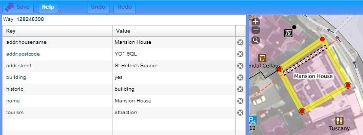
Buildings in OpenStreetMap
Similarly, all buildings contain a collection of tags. The great thing about tags is that they are an open concept – you can use any tags that you like. With buildings, the most common tags include the building name and the building type. For example:
Using Elk to extract buildings
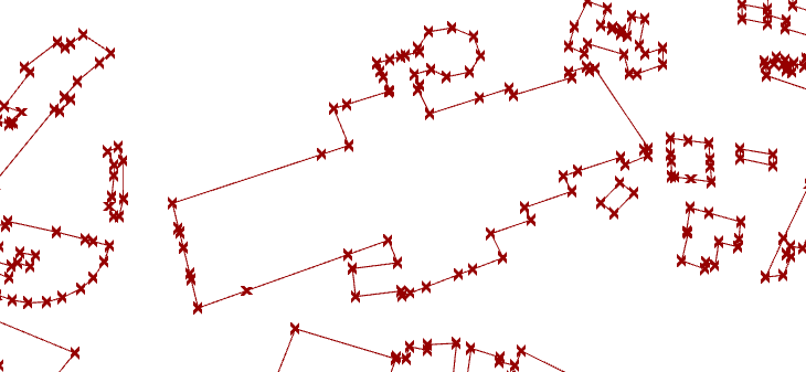
Elk can be used to extract the points that form the building outline. Like polylines in Rhino, the data is saved as a collection of points, and not a line itself, so it will be up to us to stitch the points together to create a building outline.
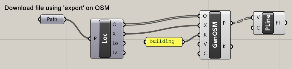
There is no built-in component that returns directly the building points, but we can use the GenericOSM to filter for data containing the ‘building’ key. The Polyline component joins the points together.
Make your buildings 3D
This is all well and good, but don’t they look a bit flat and boring? Let’s make them look a bit more realistic.
The easiest way to turn your polylines into 3D buildings is to extrude them, and then use patch to create a roof. But I can tell you through my own experience that this is a bad idea. For a few buildings it’s okay, but for the city scale, working with surfaces is very slow and you’ll quickly see your computer grind to a halt. To build our buildings at lightning speed, we have to use meshes.
There isn’t anything natively in Grasshopper that does this for us, but we can quickly write something in C#. Basically, we build up the walls with mesh faces, then use a Rhino command to cap the top for the roof.
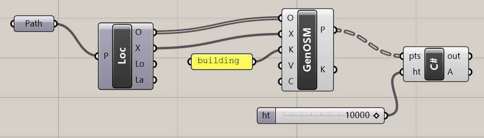
This script takes in a list of points that describe the building outline, and a value for its height. (Let’s just send it a value of 10m or so for now.)
privatevoid RunScript(List<Point3d> pts, double ht, refobject A)
{
var building = new Mesh();
//make wallsfor (int p = 0; p < pts.Count; p++)
{
building.Vertices.Add(pts[p]);
building.Vertices.Add(new Point3d(pts[p].X, pts[p].Y, pts[p].Z + ht));
}
for (int p = 0; p < pts.Count - 1; p++)
{
int j = p * 2;
building.Faces.AddFace(j, j + 1, j + 3, j + 2);
}
//make roofvar roofpts = new List<Point3d>();
for (int p = 0; p < pts.Count; p++)
{
roofpts.Add(building.Vertices[p * 2 + 1]);
}
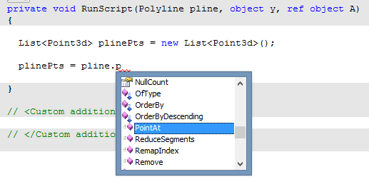
var pline = new Polyline(roofpts);
var roof = Mesh.CreateFromClosedPolyline(pline);
building.Append(roof);
A = building;
}
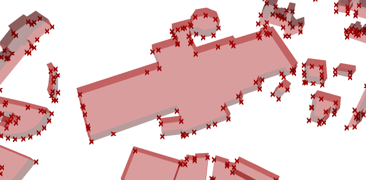
This then gives us:
But not all buildings are 10 metres tall…
It made things a lot easier to assume a height for our buildings. But can we do any better?
Given that we have a height input, we should be able to put something a bit more sensible into it. Some buildings in OSM do come with height data, though most don’t. If they do, this information is under the height key. How can we extract the building’s height information and apply it to our buildings with Elk?
It currently isn’t easy as there isn’t a comprehensive tag filter within Elk. One solution is to use the GenericOSM with k=height. This will return everything with height data; we just have to assume that everything returned is a building (it usually is) and model it as such.
Set up your Grasshopper as below, using the same C# script as above to create the buildings:
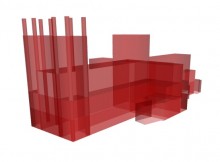
For my example of York, barely a single building has any height data. But, very happily, one very patient mapper has recorded the height of all the different elements of York Minster, leading to a very pleasing model.
But I really want heights on ALL my buildings!
Then you’ll likely have to pay up.
At least in the UK, the only near-comprehensive source of building heights is via the Ordnance Survey Topography Layer. Limited amounts of data are available as free academic licences, but otherwise it ain’t cheap.
In the meantime, if you’ve made it this far, you’ve probably realised that there are a lot of gaps in the OSM database. These gaps are best filled by people with local knowledge where you live, so I would encourage you to register and to start mapping! 🙂
Since my post last year on modelling cities in Grasshopper, I have learnt a few more things in how to get the most out of Grasshopper. I am now much more adept in using meshes, a much lighter data type than surfaces, and I have learnt a few more tricks in getting the buildings to look a little more building-like.
The combination of these means that I can now load in much larger areas into Grasshopper with much better performance. I decided to revisit the challenge of opening cities in Grasshopper and see where I could take it.
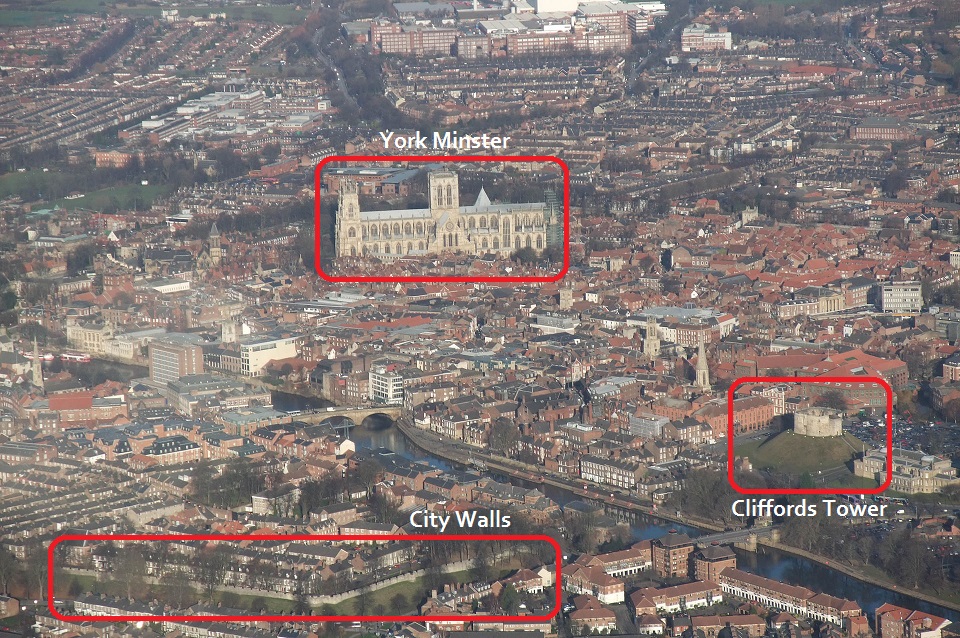
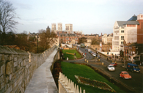
The city of York
In this post, I have modelled my historic home city of York. It is famous for its Minster and for its City Walls, and also has two rivers, numerous parks, and other historical buildings, which should make for some interesting renders.
As in my previous attempts, I am using OpenStreetMap map data. I download a map on the OSM export page, which provides an OSM file. I then use the Elk plugin for Grasshopper.
I have set up a standard Grasshopper file where I can connect it to any OSM file, and with no user intervention, it will generate a 3D model of the map data in this OSM file. The Grasshopper file is available here.
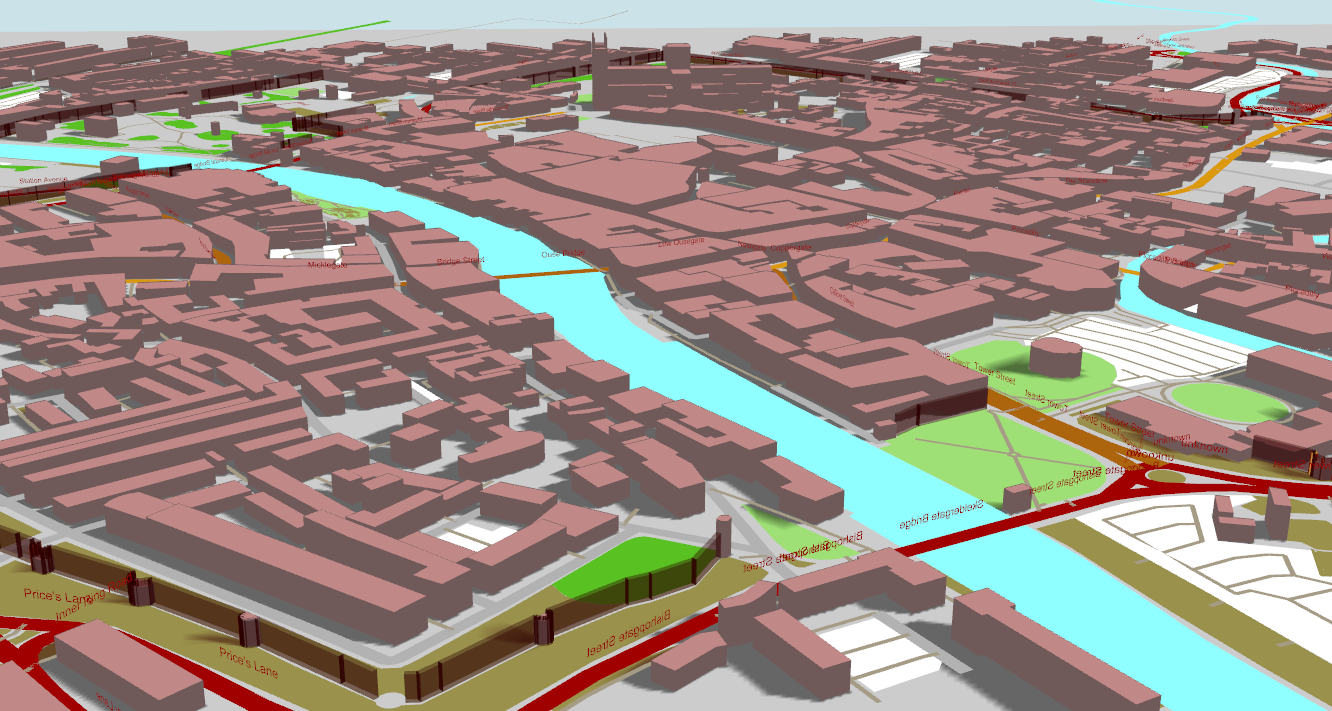
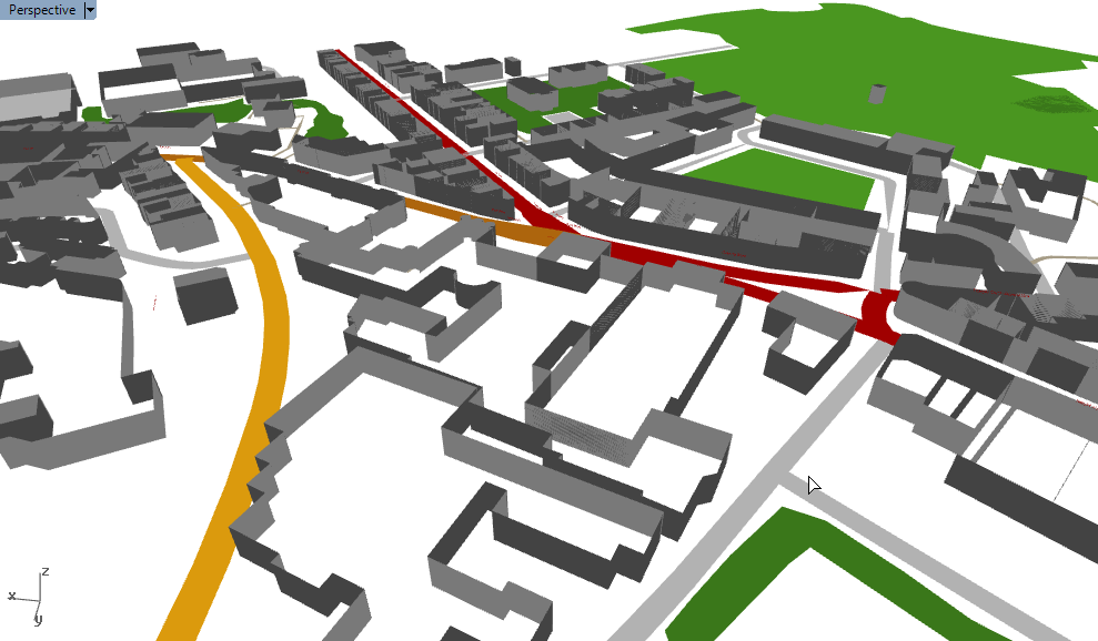
Results
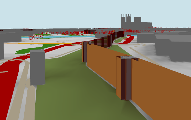
Here is the above photo modelled in Grasshopper:
The buildings are mostly modelled using their outlines, which are available for most city centre locations and key landmarks. A very few buildings also have building height data, which allows the Minster to be modelled well. All buildings without height data are instead modelled by a random height of between 5 and 15 metres. (This gives a slightly more realistic appearance than, say, having all buildings to be 10m tall.)
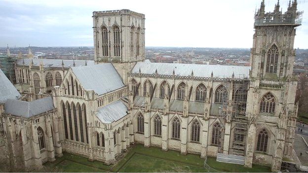
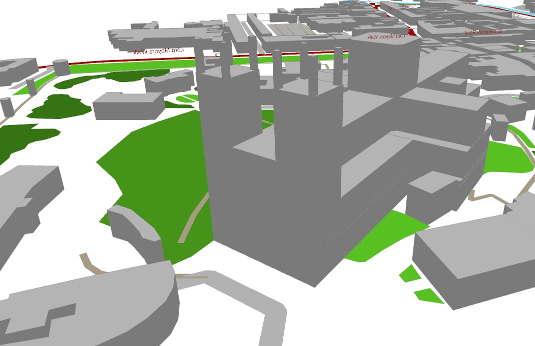
York Minster
York Minster is a highly impressive structure, towering over the rest of the city.
Somebody has spent a lot of time and effort not only entering the height and outline of the Minster into the OSM database, but recording the heights and outlines of all the individual elements of the building. This means that we get a surprisingly intricate model of the Minster out of the box with no user intervention.
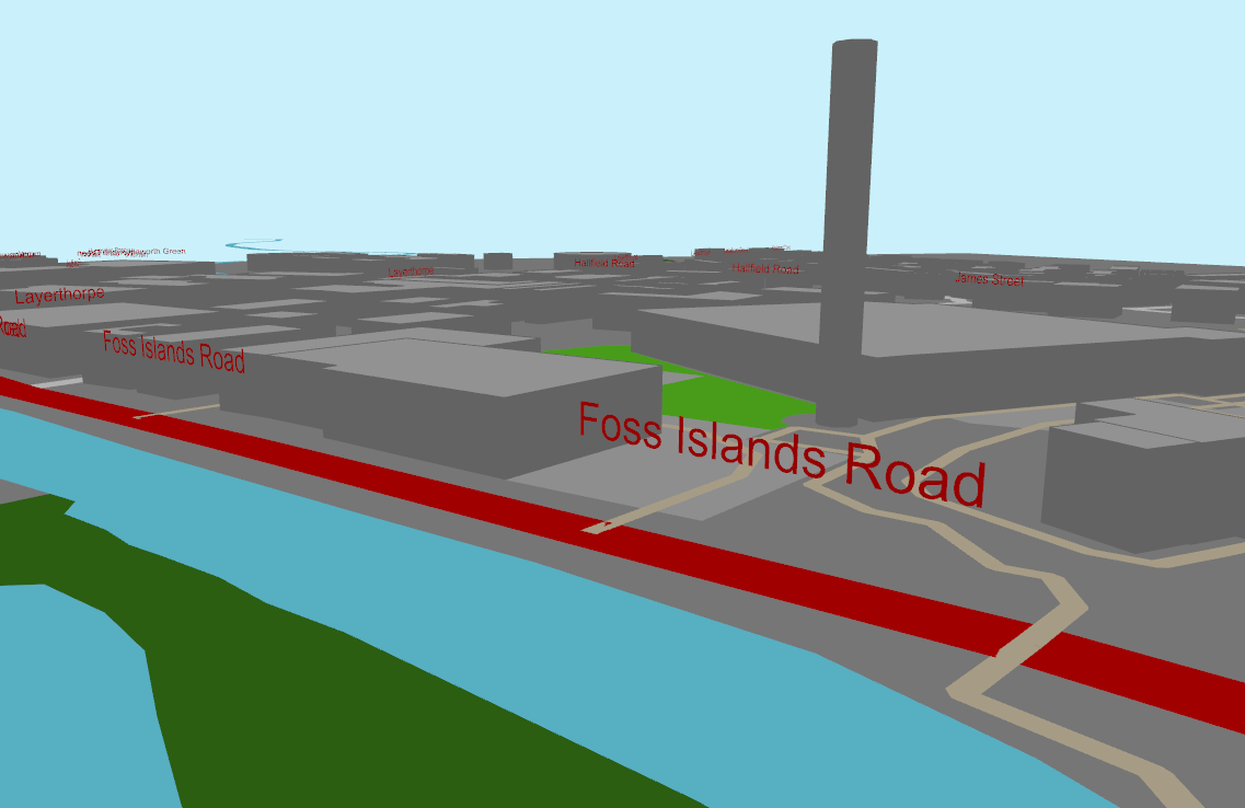
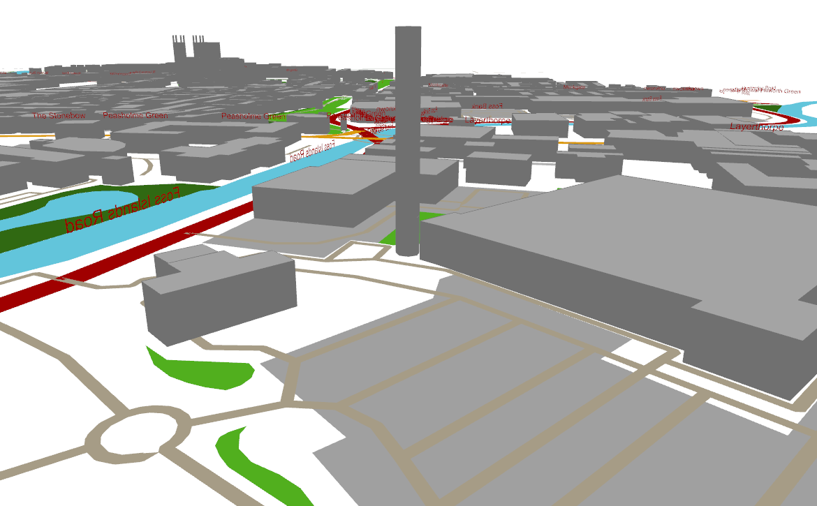
Foss Islands Road
Foss islands is an old industrial area near the city centre which is now mostly devoted to retail. A key landmark remains – an ominous Victorian chimney which stands slightly out of place next to a Morrisons supermarket.
Unfortunately there is no automatic way to model the grass banks around the walls, but the walls are saved as polylines in OSM. These walls are made by converting the polylines into 2D meshes (the same as how the roads are generated) and then extruded 10m up. They are quite jagged though and could do with some more work.
C# code and links
Some key code snippets used:
Roads
OSM roads are effectively polylines. In order to render them with colours, they need ‘expanding’ into 2D shapes that have a width. This is done by creating a mesh face for every polyline segment. The component for this is available here.
Buildings
Here is a more in-depth discussion on how to create buildings in 3D using OpenStreetMap data.
How to read the normal of a mesh in Grasshopper in C#, and flip the mesh if the normals are facing the wrong way.
Creating city buildings in Rhino
I recently revisited the task of generating cities in Rhino using Elk. One of the problems with this original solution was that I had no fast way of generating the roofs of the buildings. The most obvious solution to generate the building roofs was to use the ‘patch’ function of Rhino using the building outline as input. But surfaces are data- and processor-heavy, and files at the city scale would crash the computer. So I left the roofs out…
Meshes are much lighter data structures than surfaces, and should be used where possible where performance is an issue. In this post, meshes were created by casting curves to meshes.
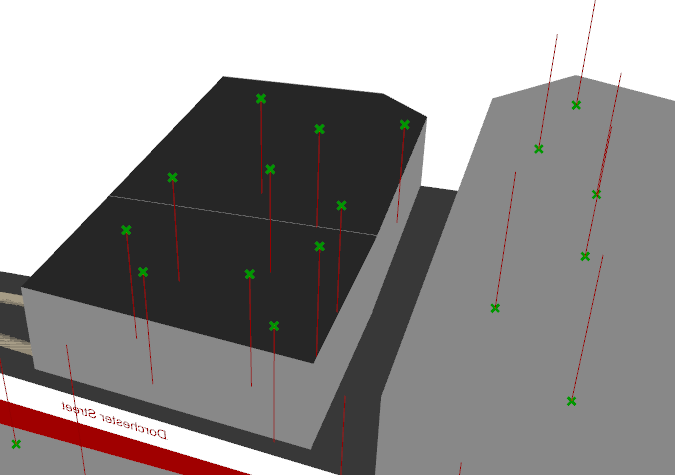
Mesh orientation
This works well, but the output meshes do have rendering issues. All mesh faces have a direction (a front and a back) and Rhino renders the mesh differently depending on what side it thinks it’s looking at. It is apparently quite random whether the above meshing trick generates a mesh which faces upwards or downwards.
Flip backwards meshes
The solution is to ‘flip’ the offending meshes so that all meshes are facing the same way. The challenge lies in detecting the meshes which are facing the wrong way, and then to find a way to flip these meshes. The tidiest way is to do this with a C# component.
privatevoid RunScript(object x, object y, refobject A)
{
Mesh mesh = (Mesh) x;
for(int i = 0; i < mesh.Faces.Count; i++)
{
var normal = mesh.Normals[0];
if(normal.Z < 0)
{
mesh.Flip(true, true, true);
}
}
A = mesh;
}
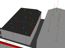
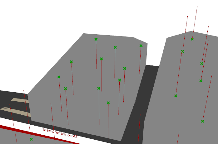
The result is that the roofs now are all the same colour. The red lines, representing the normals of the mesh faces, are all now facing the same direction.
How to call and calculate a Grasshopper component from within some C# code, and read and return the component outputs.
A Grasshopper component is essentially a visual interpretation of a method in programming. It has inputs, it does calculations, and it produces outputs. Grasshopper components are also saved within DLL libraries, and can be referenced. So, surely, it’s possible to access a component programatically from within something like a Visual Studio project? This is a quick first attempt to do so.
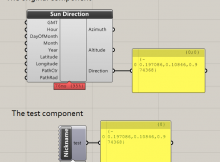
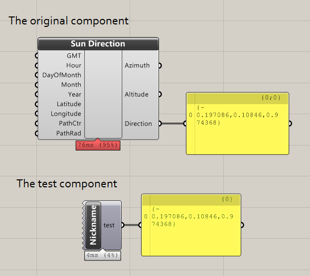
The code below attempts to read one of my own components (“CalcSunDirection”). The component runs with all inputs at default values, and then returns the first data item within output 2 (the third one in human-speak). This is copy-pasted from the Solve_Instance method when creating Grasshopper components in Visual Studio.
protectedoverridevoid SolveInstance(IGH_DataAccess DA)
{
//Create the component and run calculationsvar cs = new MyComponents.Components.CalcSunDirection();
cs.CreateAttributes();
cs.ExpireSolution(true);
//add to document
GH_Document GrasshopperDocument = this.OnPingDocument();
GrasshopperDocument.AddObject(cs, false);
//read output[2]
cs.Params.Output[2].CollectData();
var rtnval = cs.Params.Output[2].VolatileData.get_Branch(0)[0];
//remove that component
GrasshopperDocument.RemoveObject(cs.Attributes, false);
//send output
DA.SetData(0, rtnval);
}
As we can see, the test component produces the same output as the CalcSunDirection component it is referencing. The above image is for comparison – in reality, the user wouldn’t see the CalcSunDirection, only the Test component.
I believe it is hypothetically possible to do this trick with any component, assuming that the DLL/GHA file containing the component you want to use is referenced in your Visual Studio project.
I tried to do this with some native Grasshopper components (such as the circle from CNR component). I looked up the namespace of the component using this tool, but I had trouble locating the DLL containing the component, so I was unable to add it to my VS project. (For example, the Circle CNR component has namespace CurveComponents.Component_CircleCNR, which is not within Grasshopper.dll. Anyone have any idea where I can find it?) Edit – found them! See below…
As a first attempt, the code above also seems inefficient in that you have to physically add the component before the outputs become readable. I get around this from a user experience point of view by removing that component after, but computationally, it still feels heavy and unnecessary.
Upon reflection, what I’ve essentially created is a programmatic version of the clustering feature of Grasshopper. Is this the best way to go about it? If you have any interesting suggestions, please let me know 🙂
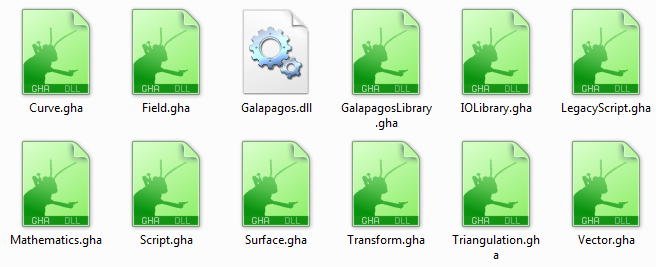
If you are struggling to find them, and you don’t mind giving third party software direct access to your computer’s Master File Table (!), then UltraSearch is the fastest way to find the GHA files.
Within this folder is a collection of GHA files (which is essentially a DLL with the extension changed).
The full list is:
Curve.gha
Field.gha
Galapagos.dll
GalapagosLibrary.gha
IOLibrary.gha
LegacyScript.gha
Mathematics.gha
Script.gha
Surface.gha
Transform.gha
Triangulation.gha
Vector.gha
So for the Circle CNR component, I would find it by referencing the Curve.gha file.
Update 2
See this post for updated code. This updated code allows you to create a dummy document, so you don’t need to paste components on the live document.
How to convert a Rhino Brep to a Rhino Mesh using RhinoCommon. This method is suitable for use in Grasshopper development and the Grasshopper C# component.
Create meshes from Brep
The code below produces a list of customised meshes based upon an input Brep and some mesh settings. The examples are written as static extension classes for compiled components (so you can access it directly as a Brep method), though can be easily adapted for the C# component too.
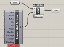
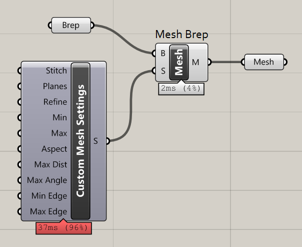
This method essentially replicates the Grasshopper components below:
The MeshingParameters class replicates the ‘Mesh Settings’ component. You can assign settings to your mesh by creating an instance of MeshingParameters and accessing its properties, much as I have done with MaximumEdgeLength.
Joining the meshes
The output is a list of meshes. If you want to truly replicate the Mesh Brep component, you will also need to join all meshes in the list into a single mesh. This can be done with the Append method:
publicstatic Mesh JoinMeshes(this List<Mesh> meshes)
{
var rtnmesh = new Mesh();
foreach (Mesh mesh in meshes)
{
rtnmesh.Append(mesh);
}
return rtnmesh;
}
And for completeness, you can call the methods in a single line:
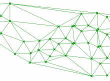
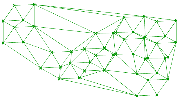
How to perform a Delaunay triangulation on a list of points mapped in 2D, using the C# component in Grasshopper.
Delaunay triangulation is a highly efficient algorithm which creates a triangulated mesh from a collection of points. This page shows how to create a 2D mesh from a collection of points on the XY plane.
Input
A list of Point3d. These points should already be mapped onto a 2D plane – ideally onto the XY plane.
If your points aren’t mapped onto a 2D plane, you’ll need to do this in advance. The reason for this is that the Delaunay triangulation algorithm below uses the Node2 type – essentially like a point, but only with X and Y coordinates – since this algorithm produces a 2D mesh.
Output
A regular, Grasshopper-friendly mesh.
Steps
Convert Point3d into Node2
Add Node2 to Node2List (that’s a list of Node2s, not “node-to-list”!)
Calculate connectivity of mesh faces
Construct and return mesh
C# code
The code below uses Grasshopper.dll to perform the Delaunay triangulation.
//input
List<Point3d> pts;
//convert point3d to node2//grasshopper requres that nodes are saved within a Node2List for Delaunayvar nodes = new Grasshopper.Kernel.Geometry.Node2List();
for (int i = 0; i < pts.Count; i++)
{
//notice how we only read in the X and Y coordinates// this is why points should be mapped onto the XY plane
nodes.Append(new Grasshopper.Kernel.Geometry.Node2(pts[i].X, pts[i].Y));
}
//solve Delaunayvar delMesh = new Mesh();
var faces = new List<Grasshopper.Kernel.Geometry.Delaunay.Face>();
faces = Grasshopper.Kernel.Geometry.Delaunay.Solver.Solve_Faces(nodes, 1);
//output
delMesh = Grasshopper.Kernel.Geometry.Delaunay.Solver.Solve_Mesh(nodes, 1, ref faces);
What next?
Delaunay meshes are pretty amazing. They are quick to generate, quick to analyse and quick to render. They generate sensible triangulation and require no more information than the input points. Unless you absolutely must have smooth surfaces and edges, don’t use a surface, use a mesh.
This video uses Delaunay triangulation to power the graph in the bottom left. The graph was easily coloured by associating each node in the mesh with a value.
These posts will help you get started in making the most of your mesh:


