Grasshopper: Front and Centre for aligning legends to the Rhino Viewport

Grasshopper is a great way of creating legends and graphs beside your model, but how do you display them? You can use multiple viewports, but this is clumsy to set up. You could use Ladybug’s approach of keeping the legend close to your geometry in 3D space, but this means you have to move the viewport to inspect the legend.

legend1

Front and Centre is a Grasshopper cluster which moves legends or any other geometry directly in front of the camera. Add a timer and the legend automatically follows the camera. It intelligently scales the geometry to fit within the screen, and you can customise the location by modifying a centre point.

legend2

To use, connect the legend or geometry you wish to display to ‘Geo’. Optionally, you can add a point to define the centre of your screen to ‘pt’. Both these should be located somewhere in the plane Z=0.

frontandcentre

A simple timer example for the Grasshopper C# component

grasshopper-timer

Create a simple timer in Grasshopper using the built-in C# component with this example script.

What this does

Set runtimer to true. The component will build a list of the current time and date, once per second.

When runtimer is set to false, the timer is turned off and the list is displayed.

Code

  private void RunScript(bool runtimer, bool reset, ref object A)
  {
    if(runtimer) Example.TurnOnTimer();
    if(!runtimer) Example.TurnOffTimer();
    A = rtnlist;
  }

  // <Custom additional code> 

  public static List<string> rtnlist = new List<string>();

  public class Example
  {
    public static System.Timers.Timer aTimer = new System.Timers.Timer(1000);

    public static void TurnOnTimer()
    {
      rtnlist.Clear();
      aTimer.Elapsed += OnTimedEvent;
      aTimer.Enabled = true;
    }

    public static void TurnOffTimer()
    {
      aTimer.Elapsed -= OnTimedEvent;
      aTimer.Enabled = false;
    }

    private static void OnTimedEvent(Object source, System.Timers.ElapsedEventArgs e)
    {
      rtnlist.Add(e.SignalTime.ToString());
    }
  }

Download

You can download the above code as a Grasshopper user object here


Further information

MSDN guide: timers in C#

Grasshopper timer using Python

If you are looking to add a timer to a Python component without using the timer component, have a look at Anders Deleuran’s code here.

Set the Rhino camera with Grasshopper and C#

Setting the camera in Rhino can be a bit fiddly. Often, dragging and orbiting doesn’t give you the camera view you need. It is possible to manually set the camera using the ViewportProperties command, but even this often isn’t ideal.

However, it is surprisingly easy to set the Rhino camera with a few lines of C# code in Grasshopper. The key part is understanding how the Rhino camera works. The camera location is defined by a Point3d. In order to get the view direction, a second point is used, called the target. So if you want to ‘look around’, keep the camera location constant, and move the target. If you want to orbit around an object, keep the target the same and move the camera location. If you want to ‘walk’ (like in Sketchup) then you need to move the location and the target together.

To use the code below, create a C# component in Grasshopper. Copy the script below into the component. The snippet gets the camera in the selected Rhino viewport.

Get camera

private void RunScript(bool getcamera)
{
    //get current viewport    
    vp = doc.Views.ActiveView.ActiveViewport;
    //save camera location and camera target
    loc = vp.CameraLocation;
    tar = vp.CameraTarget;
}
// <custom additional code>

Rhino.Display.RhinoViewport vp; //used to get and set rhino camera properties
Point3d tar;
Point3d loc;

…and this one sets the viewport. You’ll need to set two Point3d inputs called loc and tar to take the user’s desired camera location and target points.

Set camera

private void RunScript(Point3d loc, Point3d tar)
{
    //get current viewport    
    vp = Rhino.RhinoDoc.ActiveDoc.Views.ActiveView.ActiveViewport;
    //set new camera
    vp.SetCameraLocations(tar, loc);
}
// <custom additional code>

Rhino.Display.RhinoViewport vp; //used to get and set rhino camera properties

These examples are of course very simple, but you don’t have to stop here. Once you’ve got the gist of it, this approach reveals not only the ability to manipulate the view but it allows a huge range of creativity. For example, I rendered OpenStreetMap data in Grasshopper and manipulated the camera to follow a road.

You can download the Grasshopper file to set the camera along a curve like the above video from here.

Vastly improve Grasshopper component performance by NOT using data types??

Scripting components in Grasshopper can be a great way to get extra power and functionality for those comfortable with C# or VB. It can also be a much tidier way of doing certain tasks than using components, such as using mathematical formulae on a list of values.

Calculating the minimum value in a list of numbers is a great example of this – difficult to do using Grasshopper but dead easy with a few lines of script. The algorithm is simple – look through every item in the list, keeping track of the smallest item found. When we are at the end of the list, simply return this smallest value.

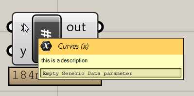
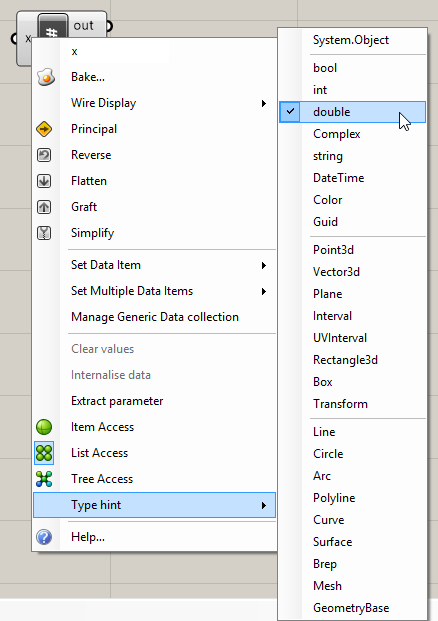
To implement this in Grasshopper, we can use the C# component. We’d start by specifying the input data types by right-clicking on the input, selecting ‘list’ and selecting ‘double’.

GH_component_right_click

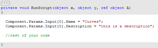
Then we’d go into the component and add our code.

  private void RunScript(List<double> x, ref object A)
  {

    double minsofar = x[0];

    foreach(double val in x)
    {
      minsofar = Math.Min(val, minsofar);
    }

    A = minsofar;

  }

This works fine and gives the expected result.

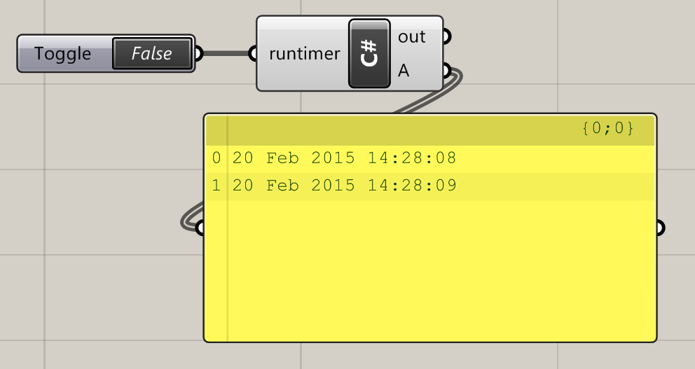
But try and run this code for quite a large list, say 100000 items. This takes around a second to compute. Not an especially long time, but for such a simple calculation it still adds a noticeable lag to the canvas. I just accepted it for what it was, thinking maybe that’s simply how long it actually takes to run a bit of code.

One day, I was writing another simple component and was feeling especially lazy. I couldn’t be bothered to do the right-clicking malarkey, and decided to just cast the data types in the Grasshopper component itself. Again, there was a large list going into the component, but to my surprise it calculated in mere milliseconds. Investigating further, I found that this speed difference occurs time and time again, and can be easily demonstrated:

GH_double_cast

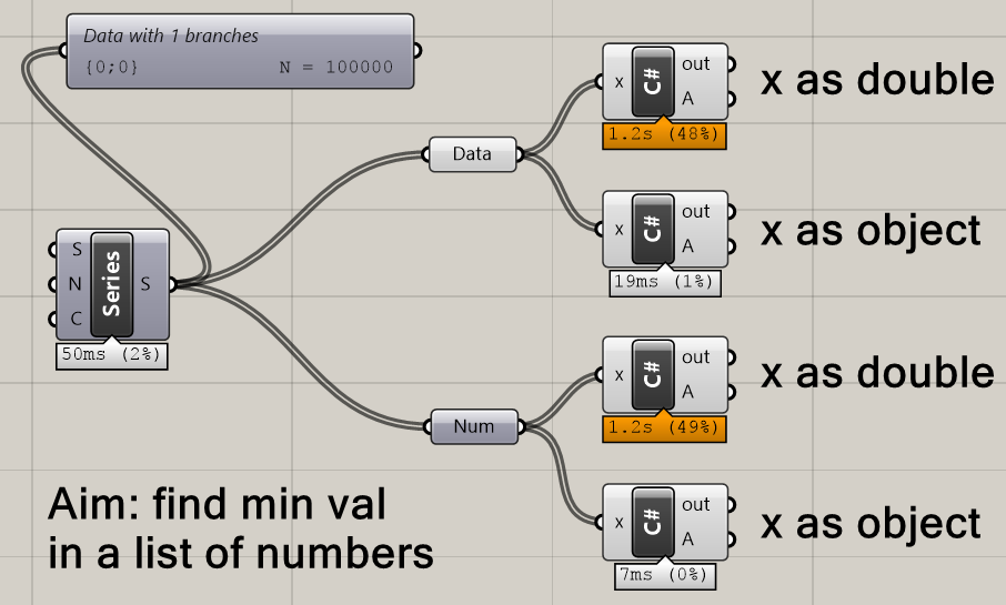
Here, we have a list of 100000 numbers (a series of doubles) and we’re trying to find the smallest value among them. (Of course, with an ascending series it’s going to be the first value, but the algorithm doesn’t know that.) The code for the first C# component is:

    double minsofar = x[0];

    foreach(double val in x)
    {
      minsofar = Math.Min(val, minsofar);
    }

    A = minsofar;

This is the same as before – we have set the input data type (called x) as double, and assumed that x is a double in the code. This consistently takes 1.2s to calculate on my laptop.

The code for the second C# component is:

    double minsofar = (double) x[0];

    foreach(object val in x)
    {
      minsofar = Math.Min((double) val, minsofar);
    }

    A = minsofar;

The only difference here is that we don’t tell the component input to expect a particular data type – we leave it set as ‘object’. (We still have to tell it it’s going to be a list.) Then, in the code, whenever we want to do something with this list that can only be applied as numbers, we cast the item in the list we are looking at as a double, e.g. x[0] becomes (double)x[0].

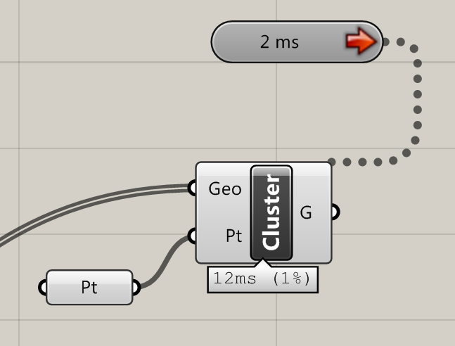
The difference this makes is astonishing – we go from a calculation time of 1.2s to a tiny 7 milliseconds.

Why this is I don’t know. Whether it works for other data types I am still investigating, and it would be great to hear if this technique is repeated elsewhere in different scenarios.

In the meantime, the lesson is clear: if you are looking to optimise your canvas as much as possible, it is worth trying to cast your variables inside your component instead.

Download the example file:

Changing input names for custom C# Grasshopper components

Edit input names of a GH component

The two components above look similar but are actually the same. What’s the difference? When a single item is connected to the first input, saving is enabled in the bottom input. When a list is connected to the first input, saving is disabled.

When we are writing custom Grasshopper components in C# in Visual Studio, this is very easy. All we do is, somewhere within the SolveInstance method, modify the input properties to change the name, then manually add some code to allow for our desired saving behaviour.

protected override void SolveInstance(IGH_DataAccess DA)
{
   if(Input0.Count == 1)
   {
       Params.Input[6].NickName = "save";
       Params.Input[6].Name = "Save";
   }
   else if (Input0.Count > 1)
   {
       Params.Input[6].NickName = "----";
       Params.Input[6].Name = "Save (Disabled)";
   }
}

In fact, by going to

Params.Input[i].something

where i is the index of the input we are interested in, we can access lots of interesting properties and methods to bring new interesting behaviour to our Grasshopper components. We can even do the same to our outputs with Params.Output[i].

And it’s not just limited to the parameter inputs and outputs either. By using

this.something

we can browse the properties and methods which affect the whole component. For example, we can add a warning to our component by adding the line below to our SolveInstance code:

this.AddRuntimeMessage(GH_RuntimeMessageLevel.Warning, "You did a booboo.");

Custom error message on a Grasshopper component

Keyboard reader for Grasshopper

A prototype way of interacting with Grasshopper with the keyboard. Press any character key on the keyboard to send true/false values to Grasshopper.

It uses the Global Mouse and Keyboard Hook classes by George Mamaladze to intercept key up/down events. I have written two components that turns these key events into true/false commands – if a key is raised, ‘false’ is sent, and if pressed, ‘true’ is sent.

Keyboard reader with 6 pre-filled keys

In the component above, 6 keys have been hard-coded. (I have been using this as part of video game-like WASD camera control in Rhino.) The component below accepts any character (and possibly any key on the keyboard if you’re lucky enough to find the correct character code for each key.)

Keyboard reader with any letter of the keyboard

Install

To install, download the file at the bottom of this page. Unzip and copy the two files (one GHA and one DLL) into your Grasshopper components folder. To use, set up as in the images above, and remember to attach a timer with a short interval. You may need to unblock the file within Windows if you are having problems. (Right click each of the two files in Windows Explorer, click Properties, and click Unblock.)


Source code

The source code of the Grasshopper components is available at GitHub.

The classes for interacting with the keyboard must (at least for the moment) be downloaded separately, and are available here.

Adding names and descriptions to C# components in Grasshopper

Adding names and descriptions to inputs in custom components makes it easier for other users to understand your component. You can add these even within the C# component within Grasshopper by adding a few lines somewhere within your code:

componentdescription

Then, when the user hovers over an input, it should look like this:

descriptionpreview

Rendering cities in Rhino with OpenStreetMap data

This slideshow requires JavaScript.

Using the freely available map data from OpenStreetMap (OSM), it is possible to create maps and renders of towns and cities within Rhino.

Most of the hard work was done by the creators of Elk, a plugin for Grasshopper that parses OSM data files and returns geometry sorted into roads, rivers, railway lines and so on. It’s then just a matter of taking that geometry and modifying it to suit your visual requirements.

And once the data’s in Grasshopper, we can do all the usual crazy Grasshoppery stuff to it. In the last image above, I connected the buildings up to a bit of C# to show its distance to a given point using colour. I think I like this version of Bath more…

2015/03/31 Update: How to do this yourself

Great news! After some digging around I have stumbled upon the Grasshopper definition I used to create this. If you want to do this for your own town, it is quite simple:

  1. Visit OpenStreetMap. Zoom into the area of interest, click ‘Export’ at the top, and then the blue ‘Export’ button on the left. The file size should be much less than 10MB for decent performance. If the file is too big then zoom in and try again.
  2. Download Elk – which provides the Grasshopper components to parse the OSM file
  3. Download my Grasshopper definition and open it in Grasshopper. At the very left, import the OSM file.

This definition was made many months ago when my knowledge of meshes (and how to make them faster) was much less. I’ve since become more proficient in making really lightweight meshes. I think that Grasshopper can handle much larger maps than this current definition will allow, and one day I plan to see how far I can take it. But this will have to do for now 🙂

2015/07/11 Update 2

As promised, I have had another go at this, and I have now modelled the entire centre of my city York. Take a look and download the GH file here.

How to offset a curve in Grasshopper using the C# component

An example offset curve in Grasshopper
How to generate an offset curve in Grasshopper using only C#, either in the C# component or with Visual Studio:

NurbsCurve crv = new NurbsCurve(inputCurve.ToNurbsCurve()); //input curve to use as offset base
Point3d origin = new Point3d(0, 0, 0);
Vector3d vectxy = new Vector3d(0, 0, 1);
Plane xy = new Plane(origin, vectxy);
Curve[] crv4 = crv.Offset(xy, 1, 0.01, 0); //Get the offset curve array
NurbsCurve[] crv3 = new NurbsCurve[crv4.Count()]; //Make a new array with the size of crv4.count
for (int x = 0; x < crv4.Count(); x++)
{
    //Loop through the Curve[]
    crv3[x] = new NurbsCurve(crv4[x].ToNurbsCurve()); //Convert each Curve into a NurbyCurvey
}

Note that the offset function returns as a Curve[], and that the ToNurbsCurve() method can’t be used directly with arrays. The above code attempts to get around these limitations.

The mesh data structure in Grasshopper

Understanding meshes in Grasshopper can be a little tricky. They have a somewhat unintuitive data structure that can make it hard to handle meshes in C# code.

You probably already know a little about meshes. They are a form of geometry that contain a collection of faces, and that each face can have no more than 4 corners. How does Grasshopper handle this?

The basics

A mesh is a collection of faces. Each face is defied by 3 or 4 vertices. A vertex is a 3D point. A single mesh can contain as many faces and vertices as you want.

A mesh sphere in Grasshopper, indicating mesh points (vertices) and mesh faces


In terms of data structures, a mesh contains 2 lists:

  • A list of faces
  • A list of vertices

Firstly, we define a list of vertices. This is a list of 3D points. For each point, we can also imagine an index. For example, the fourth point in the list has an index of 4.

Then, we define each face. For each face, we define three vertices for triangles called A, B and C, or four vertices for quads, A, B, C and D. In the face list, the vertices contain the indices for the vertices, and not the coordinates of the vertices themselves. This is important to remember!

What does this mean when Rhino reads this data and tries to display a mesh? Take the example in the image below.

A table with an example showing how mesh faces and mesh vertices are held in the mesh data structure

The mesh contains 3 faces. For the first face, we have three values and therefore three vertices, so face 1 is a triangle. What are the coordinates of these three vertices? To do this, we need to also look at the vertices list. Face 1 contains vertices 4, 5 and 3. Remember, these are the indices for our vertices. We take these three values and cross-reference them with the vertex list – reading the coordinates for vertices 3, 5 and 4.

Why is it so complicated?

The above system actually makes sense from a data efficiency point of view. Of course, in most meshes, multiple faces will share vertices. With the sphere above, each vertex is shared between 4 neighbouring faces. With the above data structure, we only need to define our mesh points once.

Furthermore, if we want to move a point on our sphere, we just have to update our vertex list. We don’t have to search for every copy of a node or worry about ‘breaking’ our mesh when we move mesh points about.

Manipulating meshes: A C# example

Create a C# component in Grasshopper. Create an input called ‘mesh’ and set its data type to Mesh.

  private void RunScript(Mesh mesh, ref object A)
  {
    //1) Let's read from an existing mesh

    //get faces from mesh
    List faces = new List();
    foreach(MeshFace face in mesh.Faces)
    {
      faces.Add(face);
    }

    //get vertices from mesh
    List vertices = new List();
    foreach(Point3d vertex in mesh.Vertices)
    {
      vertices.Add(vertex);
    }

    //2) Let's get the coordinates for a mesh face
    
    //get the indices for the 10th face
    int[] indices = new int[4];
    indices[0] = mesh.Faces[10].A;
    indices[1] = mesh.Faces[10].B;
    indices[2] = mesh.Faces[10].C;
    indices[3] = mesh.Faces[10].D;

    //We can now get the coordinates for the 10th face from these indices
    Point3d[] facepts = new Point3d[4];
    for (int i = 0; i < 4; i++)
    {
      facepts[i] = mesh.Vertices[indices[i]];
    }


    //3) Let's make a new mesh from scratch
    
    Mesh rtnmesh = new Mesh();
    //for the new mesh, we first need to define the vertices
    //we can add any points we like - let's just copy over the vertices list
    rtnmesh.Vertices.AddVertices(vertices);
    //now let's make a face and add it to the (currently empty) face list
    MeshFace tempface = new MeshFace(0, 1, 12, 11);
    rtnmesh.Faces.AddFace(tempface);

  }

Download an example

The code above is available in the file below.

Download