Adding names and descriptions to C# components in Grasshopper

Adding names and descriptions to inputs in custom components makes it easier for other users to understand your component. You can add these even within the C# component within Grasshopper by adding a few lines somewhere within your code:

componentdescription

Then, when the user hovers over an input, it should look like this:

descriptionpreview

How to offset a curve in Grasshopper using the C# component

An example offset curve in Grasshopper
How to generate an offset curve in Grasshopper using only C#, either in the C# component or with Visual Studio:

NurbsCurve crv = new NurbsCurve(inputCurve.ToNurbsCurve()); //input curve to use as offset base
Point3d origin = new Point3d(0, 0, 0);
Vector3d vectxy = new Vector3d(0, 0, 1);
Plane xy = new Plane(origin, vectxy);
Curve[] crv4 = crv.Offset(xy, 1, 0.01, 0); //Get the offset curve array
NurbsCurve[] crv3 = new NurbsCurve[crv4.Count()]; //Make a new array with the size of crv4.count
for (int x = 0; x < crv4.Count(); x++)
{
    //Loop through the Curve[]
    crv3[x] = new NurbsCurve(crv4[x].ToNurbsCurve()); //Convert each Curve into a NurbyCurvey
}

Note that the offset function returns as a Curve[], and that the ToNurbsCurve() method can’t be used directly with arrays. The above code attempts to get around these limitations.

The mesh data structure in Grasshopper

Understanding meshes in Grasshopper can be a little tricky. They have a somewhat unintuitive data structure that can make it hard to handle meshes in C# code.

You probably already know a little about meshes. They are a form of geometry that contain a collection of faces, and that each face can have no more than 4 corners. How does Grasshopper handle this?

The basics

A mesh is a collection of faces. Each face is defied by 3 or 4 vertices. A vertex is a 3D point. A single mesh can contain as many faces and vertices as you want.

A mesh sphere in Grasshopper, indicating mesh points (vertices) and mesh faces


In terms of data structures, a mesh contains 2 lists:

  • A list of faces
  • A list of vertices

Firstly, we define a list of vertices. This is a list of 3D points. For each point, we can also imagine an index. For example, the fourth point in the list has an index of 4.

Then, we define each face. For each face, we define three vertices for triangles called A, B and C, or four vertices for quads, A, B, C and D. In the face list, the vertices contain the indices for the vertices, and not the coordinates of the vertices themselves. This is important to remember!

What does this mean when Rhino reads this data and tries to display a mesh? Take the example in the image below.

A table with an example showing how mesh faces and mesh vertices are held in the mesh data structure

The mesh contains 3 faces. For the first face, we have three values and therefore three vertices, so face 1 is a triangle. What are the coordinates of these three vertices? To do this, we need to also look at the vertices list. Face 1 contains vertices 4, 5 and 3. Remember, these are the indices for our vertices. We take these three values and cross-reference them with the vertex list – reading the coordinates for vertices 3, 5 and 4.

Why is it so complicated?

The above system actually makes sense from a data efficiency point of view. Of course, in most meshes, multiple faces will share vertices. With the sphere above, each vertex is shared between 4 neighbouring faces. With the above data structure, we only need to define our mesh points once.

Furthermore, if we want to move a point on our sphere, we just have to update our vertex list. We don’t have to search for every copy of a node or worry about ‘breaking’ our mesh when we move mesh points about.

Manipulating meshes: A C# example

Create a C# component in Grasshopper. Create an input called ‘mesh’ and set its data type to Mesh.

  private void RunScript(Mesh mesh, ref object A)
  {
    //1) Let's read from an existing mesh

    //get faces from mesh
    List faces = new List();
    foreach(MeshFace face in mesh.Faces)
    {
      faces.Add(face);
    }

    //get vertices from mesh
    List vertices = new List();
    foreach(Point3d vertex in mesh.Vertices)
    {
      vertices.Add(vertex);
    }

    //2) Let's get the coordinates for a mesh face
    
    //get the indices for the 10th face
    int[] indices = new int[4];
    indices[0] = mesh.Faces[10].A;
    indices[1] = mesh.Faces[10].B;
    indices[2] = mesh.Faces[10].C;
    indices[3] = mesh.Faces[10].D;

    //We can now get the coordinates for the 10th face from these indices
    Point3d[] facepts = new Point3d[4];
    for (int i = 0; i < 4; i++)
    {
      facepts[i] = mesh.Vertices[indices[i]];
    }


    //3) Let's make a new mesh from scratch
    
    Mesh rtnmesh = new Mesh();
    //for the new mesh, we first need to define the vertices
    //we can add any points we like - let's just copy over the vertices list
    rtnmesh.Vertices.AddVertices(vertices);
    //now let's make a face and add it to the (currently empty) face list
    MeshFace tempface = new MeshFace(0, 1, 12, 11);
    rtnmesh.Faces.AddFace(tempface);

  }

Download an example

The code above is available in the file below.

Download

How to automatically get the measurement units in Grasshopper/Rhino

How to automatically find out if your Rhino document is set to millimetres or metres:

private void RunScript(ref object scale)
  {
    int rtnval = 1;
    Rhino.RhinoDoc  doc = Rhino.RhinoDoc.ActiveDoc;
    Rhino.UnitSystem  system = doc.ModelUnitSystem;
    if(system.ToString() == "Meters") rtnval = 1;
    else rtnval = 1000;
    scale = rtnval;
  }

This script returns a value of 1 if the document is in metres, or 1000 otherwise. (I assume that the user will only be using mm or m.)

To use, create a C# component in Grasshopper and copy the part between the curly brackets to the code of the C# component. Make sure that the component has an output called ‘scale’.

mm or m component

…or download the component from below:

Download

Create keyboard shortcuts for coding in C# using AutoHotKey

AutoHotKey is a remarkably useful piece of free software which allows you to automate any repetitive keyboard or typing task. It effectively allows you to program any key, or any combination of keys, to any command of your choosing.

Here, I will show how to use AutoHotKey to make writing C# code a little faster and easier.

Continue reading Create keyboard shortcuts for coding in C# using AutoHotKey

Setting up Visual Studio Express 2012 and 2013 to write your own Grasshopper components in C#

A quick guide for setting up Visual Studio Express for developing Grasshopper components for Rhino 5. Continue reading Setting up Visual Studio Express 2012 and 2013 to write your own Grasshopper components in C#

Data trees and C# in Grasshopper

Understanding how Grasshopper handles data is crucial for taking full advantage of GH’s capabilities. For collections of data, they can either be in the form of lists or trees.

A list is a collection of items of data, in a particular order, but with no hierarchical structure. Here is a list of numbers:

Grasshopper list of numbers with series component

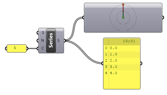
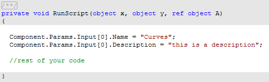
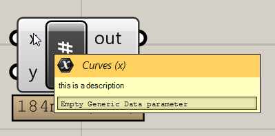
The component in the top-right is the param viewer. Double click it to see this:

Grasshopper series list with param viewer

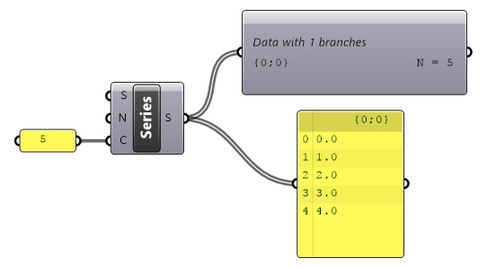
The ‘N’ denotes a list with N items. A list can be thought of as a tree with a single branch {0}. So here, we are looking at a single list, with address {0}, containing 5 items.

A tree is any data structure in GH with multiple branches. In other words, it’s a data structure with multiple lists. Each list has its own address.

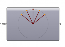
Now, let’s make a grid of points. We can do this with our list of numbers and the ‘construct point’ component.

Grasshopper construct grid of points

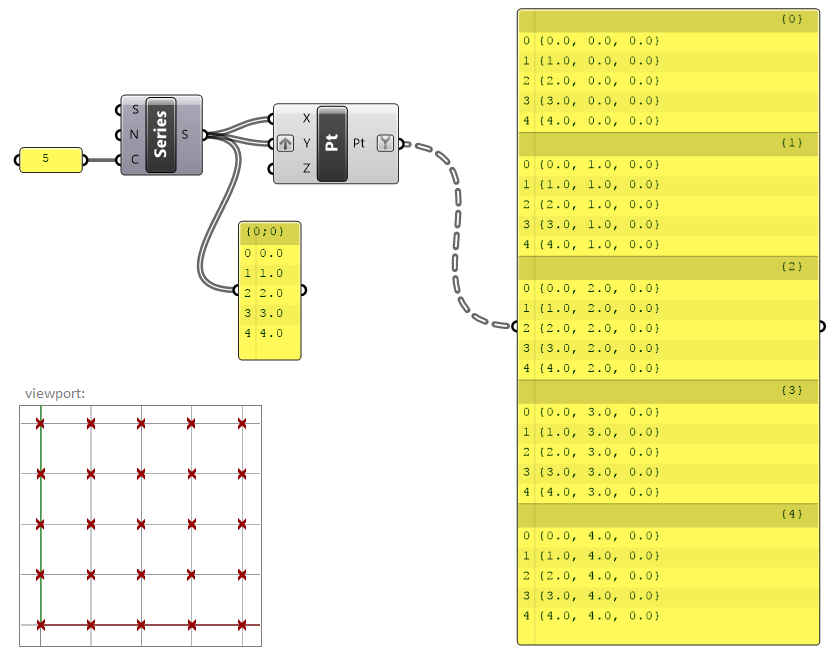
Here, we have cleverly grafted the Y input to coerce Grasshopper into giving us 25 points for our list of 5 numbers. But the output looks a little different. Instead of a list of 25 points, we have 5 groups of 5 points each.

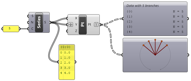
What’s happened here is that Grasshopper has created 5 branches. Each branch contains a list of 5 points. Each branch has its own address {0} to {4}, shown in the panel.

We can verify this using the param viewer.

Grasshopper param viewer for trees

Trees in C#

Trees can be created and manipulated in C# components too. When we add data to a tree in C#, we need two pieces of information:

  • The data we are saving, such as a Point3d or an integer
  • The path we are saving to

The path is declared as a list of numbers denoting the sequence of the branches needed to access the list we are interested in. As some examples:

DataTree<Point3d> myTree = new DataTree<Point3d>();
GH_Path pth = new GH_Path(2);
myTree.Add(P, pth);

point P will be written to the list at the end of branch 2.

GH_Path pth = new GH_Path(i,j)

point P will go down branch i, then be added to the list at the end of branch j

Setting up a tree

You can either add to a tree on the fly – if you know that the data in the tree will be in the same order that you’ll be adding to it. But a more flexible way is to create a blank tree of the size you want, and then edit the values later.

Setting up a tree called boolTree (I am creating a tree based upon another tree called pts):

//declare tree
DataTree<bool> boolTree = new DataTree<bool>();
//set up tree
 for(int i = 0; i < pts.BranchCount;i++)
 {
   GH_Path pth = new GH_Path(i);
   for (int j = 0; j < pts.Branch(0).Count;j++)
   {
     boolTree.Add(false, pth);
   }
 }

This has now created a tree filled with ‘false’.

Editing values in the tree

boolTree.Branch(1,2)[5] = true;

This edits the 5th value of the list at the end of branch 1, sub-branch 2 to ‘true’.